![]()
Walker on Stunt
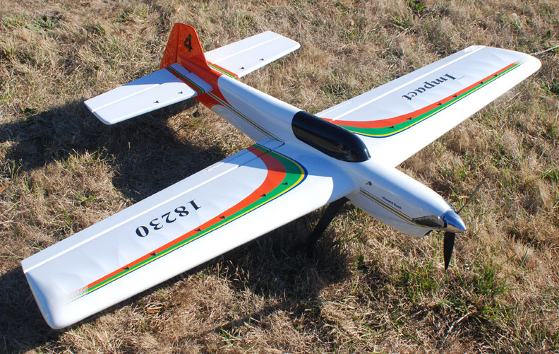
Paul Walker's Impact design has been flown by many top stunt fliers around the world. This is Howard Rush's 2015 plane, seen at the 2015 Fall Follies in Salem, Ore. Flying Lines photo.
Adjustable flap mechanism
By Paul Walker
February 2016
Welcome back. This was started as a flying column, and so far I have held to that with the discussion on trimming. However, this time I will take a slight departure from that subject to talk about how a part is constructed in my plane. Remember back to step one of the flow chart: Get the wings level. There have been different was to accomplish this by way of different materials in the flap horn, or by the McDonald socket head bolt adjusting dual flap horn. I have one of those horns in one of the B-17's. It works well but still left me thinking about my dream system. After numerous trips overseas for the World Championships and having something cause the wing flaps to need adjustment, and not having time to do the traditional hit-and-miss adjustments, I needed something better. My requirement was to have an adjusting screw that would move the flaps a set amount per revolution, and this way the adjustment is quantifiable and repeatable. A few years ago the light bulb went on and the idea germinated (finally).
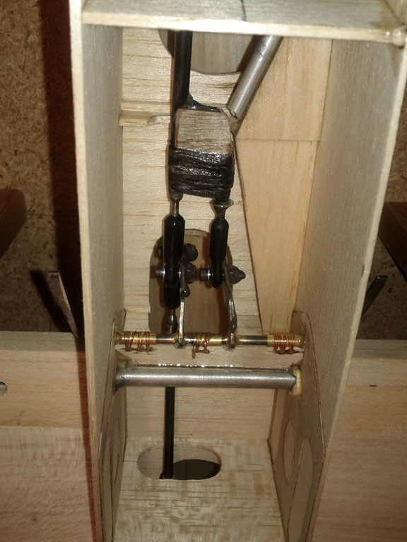 It starts with the flap horn. In this design there are “two” flap horns. Well, more like one and one half. It starts with two identical flap horns. On the outboard horn the legs is cut off just to the inboard side of the horn upright, and the inboard horn is cut just outboard of the upright. This is shown in the picture. This creates two independent horns that actuate each flap, independently. They are then attached to the wing trailing edge with three bushings, as shown.
The key element is the pushrod that connects the “flaps” to the elevator. Note that this is shown with ball links, but other clevis configurations could be used. The pushrod on the left side is identical to any pushrod with fittings glued in. The difference is the second bolt on the right side that connects the pushrod to the outboard flap. The bolt simply rotates freely in the block it is mounted in, and is constrained from moving fore-aft in that block. Thus when turned, it moves the ball link fore-aft and this is where the quantifiable and repeatable aspect comes from. To adjust it once in the model, a guide tube is installed through the fuselage side, a ball driver installed and the screw turned. This makes leveling the wings (usually) a short three flight effort. Start with the initial setting and take a short flight to check the wing level condition. Once this is ascertained, move the adjusting bolt one half turn in the direction needed. Then recheck the wing level. Now, knowing how far off it was on flight one and flight two will allow you to estimate (OK, it's an easy calculation) how much to turn the bolt before the third flight. It is usually right on at this point. Later in the trimming process, you might want to adjust the flaps one again. Now that is simple and measurable, and can also be undone to the original setting if needed.
A few words are needed for a successful assembly. The MOST important part is the pushrod. It MUST be a carbon tube with high longitudinal stiffness and bending. Why is that? Since the offset for the outboard flap exists, it produces a bending load on the pushrod. The only way to react that moment is with a lateral force on each end of the pushrod. The problem comes with using a “wimpy” pushrod. It will flex too much. Yes, it will still carry the load, but the flexure will create a differential flap motion that you don't want.
This can be seen by looking down on the system; it will rotate under load in the plane of the drawing and cause the flaps to deflect differently. Making the pushrod rigid will effectively eliminate that issue. The gap between the two flap uprights is where the twisting is generated. It is important to minimize this distance it minimize the twist. That is not easy to do with the ball links and bolts holding them to the flap horn uprights all in that tight space. I have been able to get mine about 0.65” apart using ball links in the system. So where do you get these parts. I purchased mine from Central Hobbies, in Billings, Mont. The part number for the pushrod and end fitting combination is: CHMPRS36T4.
The block that supports the adjusting bolt can be made of various materials. Alan Resinger has used this system and had this block machined from aluminum. I simply create it from some of the same tube material as the pushrod in a 1/64” ply, tube, 1/64” ply sandwich. It is seen end on in Figure 4. It is glued together with J-B Weld. This way the end hole for the adjusting bolt is already in place. Note here that the bolt I use is an 180 ksi (grade 8) 4-40 bolt 1-1/2 “ long. These are not available from your local hobby shop. I bought mine from the local high-strength bolt supplier in town. This is not a part you would want to scrimp on. When installed, make sure the retaining nut (self-locking nylon type insert) is snug but not so tight the bolt can't turn. This needs to turn easy enough so that the adjustment can be made, yet any slop here will be felt in the outboard flap, which you don't want.
One tip here is to add a guide tube so that finding the Allen head with the ball driver inside the plane is “possible.” On the first several versions I didn't extend the tube to the bolt head and just had a hardened hole in the fuse side to insert the ball driver. Finding the bolt head was problematic, and did lead to several choice words. What resulted was a “Duh” moment. Simply move the flaps to the full up position which moves the bolt head all the way aft and position the guide tube so that is almost touches that bolt head. I add a support brace of balsa on the tube to keep it in place, and then adjusting is really simple. Just move the flaps to the full up position, insert the ball driver, engage the bolt head and turn the desired amount, and you're done! Why didn't I think of that sooner?
There are a few other details worth noting. The flap horn really should be drilled and tapped for 4-40 bolts. Tom Morris has horns already drilled and tapped. The bolts I use for the ball links are also 180 ksi grade 8 bolts. The astute observer will note that per the drawing in figure 3, installing the bolt attaching the ball link to the flap horn looks impossible because of the inboard flap upright. If you tried to make that the last connection it easily could be. I install the outboard flap ball link to the upright before any of the other parts are attached. I then attach the inboard ball link that is attached to the elevator pushrod next. Then simply move the outboard flap horn upright forward and then engage the bolt in that ball link fitting and using your ball driver turn until the flaps are even with each other. At this point there should be enough threads left to move the outboard flap down more if necessary. Before installing either threaded portion into ball links, make sure the two ends of the threaded rods are even in a fore-aft direction. Then when installing the pushrod rod end into the ball link, only insert it about half way into the socket. That way when the outboard flap threaded rod is installed half way, the flaps will be close to even, and still have enough room for adjustments either way.
Picture 1 shows the system Alan Resinger used in one of his planes. It is similar to what I described but with his flare. The black joiner is machined from aluminum and anodized black. It has a wider spacing that I use, but his elevator pushrod was stiff enough to prevent any issues.
There is one last important item to consider. Since this system creates a lateral force on each flap horn, there needs to be a way to react that force so that the flap horns don't move laterally. If the flap horns are located in the flaps in the “traditional” way of drilling a hole in the flap and then installing the flap onto the horn with a forward motion, you are set. However, if you have slaps that slide onto the flap horn laterally with slots in the end, thus there is no natural way for this force to be reacted and the flap horn will move laterally under load. The flap horn will need a washer soldered to it for the bushing to ride against. Also glue a washer to the horn rod up against the upright to give the bushing a nice face to ride against. Now the bushing is trapped in-between two washers, and the bushing that is attached to the trailing edge of the wing. Now the side force will react from one of the washers to the bushing to the wing. Problem solved.
Once you use this system, you will be surprised how easy this becomes, and you will not want to go without it again.
Pushrod parts obtained from:
Central Hobbies
1401 Central Ave
Billings, MT
800 723-5937
Trim Flow Chart Chapter 1: Basic trim
Trim Flow Chart Chapter 2: Advanced trim
Trim Flow Chart Chapter 3: Criteria problems
Trim Flow Chart Chapter 4: Turning and tracking the same
Trim Flow Chart Chapter 5: Advanced trim Part 1
Trim Flow Chart Chapter 6: Advanced Trim Part 2
Back to Aerobatics section
Back to Walker on Stunt index page
Flying Lines home page
This page was upated Feb. 5, 2016