![]()
Walker on Stunt
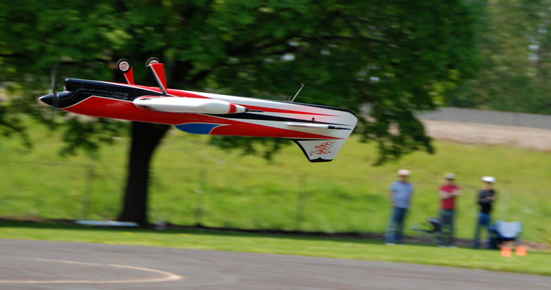
Paul Walker's 2015 Predator in flight at the 2015 Jim Walker Memorial contest in Portland, Ore. Flying Lines photo.
The trim flow chart, Chapter 4: Turning and tracking the same
By Paul Walker
June 2015
(EDITOR'S NOTE: This is the fourth installment of Paul's most recent trim flow chart update and series of articles. These articles were first published in Stunt News, the magazine of the Precision Aerobatics Model Pilots Association, and are reprinted here by permission of SN editor Bob Hunt.)
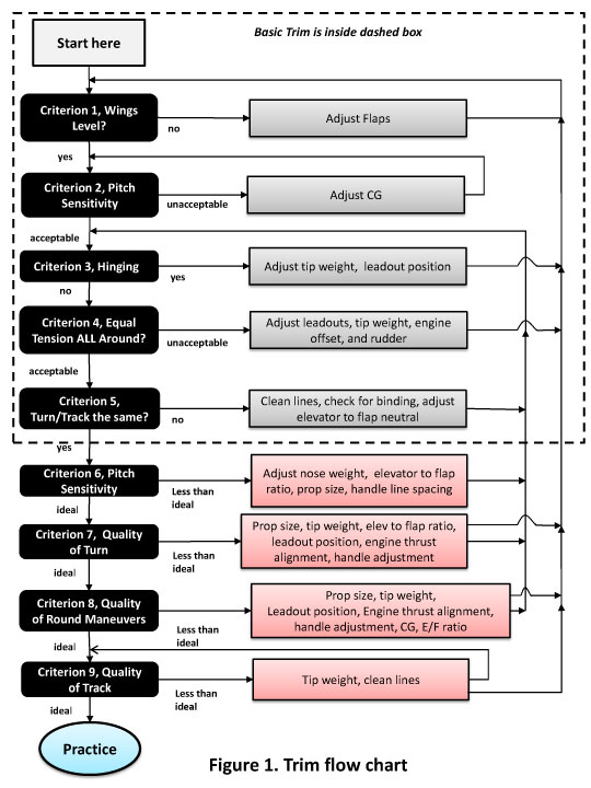
Welcome back! Once again this discussion involves the trim chart in Figure 1. This installment will be discussing criterion 5 (Turn/Track the Same), which is still in the “basic trim” section. This single criterion deserves more attention than a simple few words in a flow chart. Many of the trim changes that affect the turn rates also impact the tracking. To wade through this there is another flow chart to follow to systematically work through these trim changes to minimize time and headaches solving these criteria. The new flow chart is all inside criterion 5 in Figure 1, and is seen in Figure 2.
This flow chart could be inserted into Figure 1, but would become more difficult to put on a single page for your reference. This flow chart is still inside the basic trim section which means that the questions asked can “easily” be answered objectively. They depend on an observation that is straightforward to answer. It does require some qualitative assessment of maneuvers both inside and outside, and with a little practice will become easier to see and assess.
The goal of criterion 5 is to have the turn rates of inside and outside corners the same as well as having it track the same both upright and inverted. The previous criteria from Figure 1 adjusted the CG to make the corners manageable, leveled the wings, adjusted the leadouts, and got the tip weight in the ballpark. With that adjusted, there are still numerous adjustments that will make the corners the same if they are not. These numerous adjustments are generally, but not limited to, the elevator to flap neutral, the handle adjustment, thrust line offset, the overall 0-0-0 alignment, and possible flap warps. One item that will not be discussed here (at this point) is the engine thrust alignment.
To start the process through the flow chart in Figure 2, carefully evaluate the turn rates between insides and outsides as suggested in box 1. This can be a little tricky early on as the handle can be “out of adjustment” to compensate for this difference. If this is the case, it will usually show up as a tracking difference farther along. Fixing the tracking issue will wind you back at this square ONE (box 1) to re-evaluate the turning rates. If the turns inside and outside are not the same start by re-examining the elevator to flap neutrals, box 2. A description of this is shown in Figure 3.

Make sure that both the flaps and the elevators are at zero degrees relative to a horizontal plane. In my shop, I have a jig that the wing can sit in to locate it in a horizontal plane above the horizontal plane of the worktable. There is also a jig the stab sits in to fully support the plane. Then knowing the distance the wing centerline is above the table, the trailing edge of the flap can be measured to set it at zero degrees relative. The same procedure occurs at the elevators. The pushrod is adjusted until the flaps and elevators are both at zero degrees relative. This is then the starting point for moving to box 3. Earlier 0-0-0 alignment was mentioned. It is my preference to have the engine thrust line, wing centerline and stab center line 0-0-0. This can be described using a coordinate system for the plane. This coordinate system applied to the plane is called a global coordinate system. In this system, the x-axis is fore and aft, the y-axis is lateral (wingtip to wingtip), and the z-axis if vertical. To be 0-0-0, the engine thrust line is in an x-y plane, the wing centerline in an x-y plane as well as the stab. Each of these planes can be located in a different z, but they are all parallel. This makes the relative angle between them 0, thus the 0-0-0. Many advocate down thrust in the engine and others positive incidence in the stab, but I prefer to have mine at 0-0-0. Fiddling with one of these can be tried in the advanced trim section later on. For now, let's set it at 0-0-0 and the flaps and elevators at 0-0 as well.
If the flaps and elevators are both at zero- zero and still doesn't turn the same, try looking closely at the flaps. Check carefully to make sure they are still straight. Yes, they came out of the shop straight, but sometimes the sun, humidity, and heat can move the balsa that most are made from. If they found their way to not be straight, straighten them at this point. There are many different ways to apply heat to soften the paint/covering to allow a flex and then cool. Once it is at room temperature again, re-check for the warp. If now straight, re-install on the plane and re-test. Note that when twisting the flap you are likely to have to re-level the wing which sends you back to criterion 1 in Figure 1. Re-level the wings and carefully work your way back to this box in Figure 2 with careful observation of all the criteria in Figure 1 that gets to criterion 5.
The next step is box 4, which evaluates the pitch angle the plane makes relative to a horizontal flight path. A perfect attitude is seen in Figure 4.

The wing and stab are parallel to the horizontal flight path. This is what it SHOULD look like if all is well. However, such is not always the case. Figure 5 shows a configuration where there is a positive pitch angle where the tail is low relative to the wing.

Note that the tail could be up relative to the horizontal line as easily as down. These Figures show upright flight. Also observe what is happening in inverted flight as well. If the tail is down in upright flight and up in inverted flight, adjust the elevator down relative to the flaps. Shortening the flap to elevator pushrod will accomplish this. Keep working this loop until the question in box 5 can be answered in the affirmative. The same both ways doesn't need to be perfectly level both ways, but the same amount of pitch angle both ways. For instance the tail can be two degrees low both upright and inverted. This is an acceptable solution at this time. In fact I have seen many a stunt plane that sit tail low both ways and fly just fine. Don't get hung up on this loop trying to get it perfectly level both ways. It may never happen!
So far everything has been done following the chart and still it doesn't turn the same. Many times the adjustment of the handle is the culprit. I continue to be surprised at how I can adapt to maladjusted handles, yet still fly well. This could be getting you as well! It's time to take a close look at the handle. The first step is to check the handle neutral. If the inside corners are faster than the outside corners, then shorten the down line and try again. Conversely, if the outsides are faster, shorten the up line and try again. If this does or doesn't solve the issue, proceed to box 7 and evaluate the handle bias. Figure 6 shows a handle with no “bias”. The up line and the down line are evenly spaced about the hand and provide a balanced input to the plane. However, consider adding “bias” to the handle as described in Figure 7.
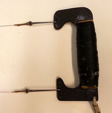
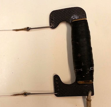
Handle bias, figures 6 and 7. Paul Walker photos.
This then provides more input on the down side and less on the up side, helping a plane that is too quick on the inside corners. Try this change and re-evaluate. Handle neutral and bias can be both off and one compensates for the other. I would suggest that the bias be set to neutral before readjusting the neutral.
After reaching this point in the flow chart and the plane still doesn't turn the same both ways, the basic geometry of the control system should be considered. In days past, the flap and elevator horns were both oriented vertically. While this is easy to see and align, it also doesn't provide a linear response with respect to bellcrank rotation. This can cause a difference in turn rates inside to outside that can be difficult to resolve. What geometry is correct to provide a linear response?
There are many variables, thus there are no “simple” answers to that question. Because of this, Howard Rush developed an Excel program that does just that task. He has shared that program with a few people, and I have used it to develop the geometry for the nonlinear system in the Predator. It has two options, one for a standard linear system and one for an Igor type nonlinear system. Howard has agreed to share this with anyone who asks him for a copy. If interested, e-mail him a request. Some knowledge of running spreadsheets and simple engineering sign convention are required to use the program correctly. As with any analysis, getting the sign convention correct is absolutely necessary for the correct answer. He will have two separate sheets defining the sign convention for both options. Study them carefully and don't be a typical male and ignore these instructions, as your results WILL suffer. Unfortunately once a full fuselage stunter is built, it is almost impossible to resolve after the build. This is part of the reason this isn't included in the flow chart. Use this program before you build your next project.
At his point in the process of following this flow chart, the emphasis turns to the tracking of the plane. The turn rates will have been dealt with as much as possible. Box 8 evaluates the tracking in level flight upright and inverted. At this point, if they track the same both ways, exit back to criterion 6 in Figure 1. However, if they are not the same, box 9 asks if the difference is “significant”. Once again, if you feel the difference can be lived with, return to criterion 6 in Figure 1. However, don't let this be a compromise at this point in time. If the plane tracks better inverted, move the elevator down relative to the flap and re-evaluate. If it tracks better upright, move the elevator up relative to the flap and re-evaluate. After these changes, box 10 asks if the balance between upright and inverted tracking is better. If not, readjust and re-evaluate. Two options exist here. The first is that tracking in now balanced between upright and inverted in which case the chart directs the user to box 1 to re-evaluate the balance of the turn rates. The second option is that after a number of cycles through this entire chart there is no satisfying the desire to have the turn rates the same and the tracking the same both inside and outside. Box 12 suggests that you select the trim adjustment that balances the turn rates as much as possible and balances the tracking inequities as much as possible and then return to criterion 6 in Figure 1.
There are many things that effect tracking. Some of them are: the right amount of tip weight, wing level condition, leadout position, and any myriad of warps. It was assumed that before entering this section that those were taken care of in the previous criteria in Figure 1. However, small amounts of each of these CAN make a difference between upright and inverted. Since this is still in the “basic trim” section, they have not been fine-tuned and may be the cause of poor tracking. The Figure 2 flow chart is intended to cover some of the “gross” issues that need to be addressed. In the advanced section, more emphasis will be placed on these issues.
This is the end of the “Basic Trim” section of Figure 1. This has been the “easy” part of the trim process. Starting next issue, the more advanced trim aspects will start to be discussed. Start thinking about what you really want your plane to do for you.

Trim Flow Chart Chapter 1: Basic trim
Trim Flow Chart Chapter 2: Advanced trim
Trim Flow Chart Chapter 3: Criteria problems
Trim Flow Chart Chapter 5: Advanced trim
Back to Aerobatics section
Back to Walker on Stunt index page
Flying Lines home page
This page was upated Sept. 1, 2015