Walker on Stunt

Paul Walker makes an official flight to win his 11th U.S. Nationals in Muncie, Ind., in July of 2015. See Paul's article on the 2015 Nats. Bob Hunt photo.
The trim flow chart, Chapter 5: Advanced trim Part 1
By Paul Walker
September 2015
(EDITOR'S NOTE: This is the fifth installment of Paul's most recent trim flow chart update and series of articles. These articles were first published in Stunt News, the magazine of the Precision Aerobatics Model Pilots Association, and are reprinted here by permission of SN editor Bob Hunt.)
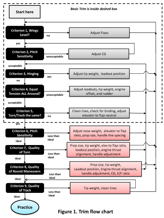
This installment of the trim discussion now moves out of the Basic trim area into the Advanced trim area. This includes criteria 6 through 9 in the trim flow chart in Figure 1. The last discussion ended with some homework to be done. The question was asked, what do you really want your plane to do for you? You honestly need to answer that question to know where you are headed. If you are satisfied with a plane that works as it does after the Basic trim area, then there is no need to follow on. If you wish to improve the scoring potential of your plane, read on.
Before proceeding into the remaining 4 criteria, you need to have some idea where you are headed. What's that you say? I know what I want. I want the highest score possible! Well, don't be so sure you really know the answer. This area of trimming is very subjective and as a result the same plane trimmed by two different pilots can and will fly differently. You need a plan and a focus for this subjective effort. Read on to find out what you really want to do to maximize your score.
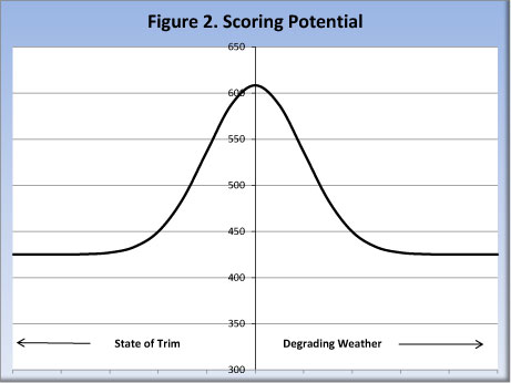
 Before we get into the details, let me digress with a discussion on how I see the performance envelope for a given plane design. Figure 2 shows what I define as a performance envelope. The Y axis (vertical) is the scoring potential for the plane and the X axis to the right of the origin is the given weather conditions (wind, rain, heat, cold, dead air, etc.) and the X axis to the left of the origin is the “state of the trim” of the model for the given weather condition. The worse the weather or the “state of trim,” the farther away from the Y axis you are. This should really be a three (or more) dimensional plot, as weather and “state of trim” can combine to make things worse, but is hard to show this effect on a two dimensional page. Don't fixate on the Y axis labels, as they are there only to show a relative value that most stunt pilots will recognize. The X axis origin is the place you want to be: Perfect weather conditions and the plane in a perfect “state of trim.” The basic idea is there even in two dimensions. Here's where it gets fun. If the trim of the plane is changed, then the shape of the performance curve is also changed. The trim of the plane is different than the “state of trim.”
“State of trim” is the trim condition at any given time relative to the trim it should be in at the time. The trim of the plane is where you have decided you want it to be. Various factors conspire to keep you from being at that ideal trim state at any given time. Changes in humidity, altitude, temperature, and your own physical and mental condition at that given time keep the plane from being at that point that you decided it needed to be. Then, the “state of trim” is that instantaneous trim point versus the desired value. The farther off of your desired trim the farther away from the Y axis you will be, and thus the scoring potential reduced. As stated earlier, your ideal trim of the plane defines the shape of the performance curve.
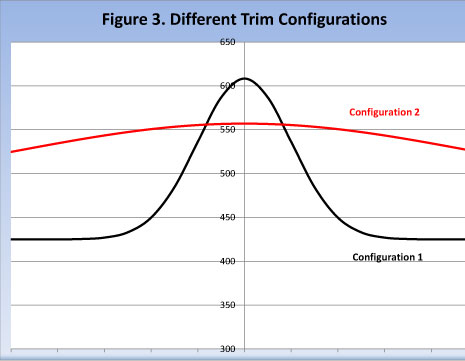
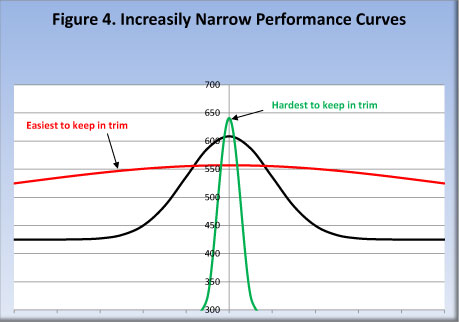
 Figure 3 shows two different trim configurations. What you should notice is that trim configuration 2 has a lower maximum scoring potential, but has a higher scoring potential when things are not in perfect “state of trim” or the weather conditions are not optimal. Yes, it seems obvious that you would want configuration 2 to give the same maximum scoring potential as configuration 1, and have a broader envelope, but that is VERY hard to achieve. The shape of these performance curves can be very narrow, and figure 4 tries to show that. The narrower the curve, the harder it becomes to remain right at the very top of the scoring potential. The broader the curve, the easier it is to stay near its maximum scoring potential, however it's maximum is lower than the narrow curve.
What makes the shape of these curves different? In general, a plane that flies more nose heavy creates a flatter curve with a lower scoring potential, and a more tail heavy plane generates a narrower peak, but has a higher scoring potential. Further, lighter planes generate broader performance envelopes as well. A plane trimmed to fly smoothly will also have a broader envelope. These are just a few examples. There are other factors that influence the shapes of these curves. Here is what you need to decide: Do you want an all-around configuration that scores well in all conditions, or one that has a higher potential but not as broad an envelope? The answer to this will drive your decision on the trim items in the flow chart. Now, is your answer still the same? Do you want to try for the maximum possible score or have a higher probability of a higher score in less than perfect conditions? You decide!
Where do I tend to fall into this discussion? I tend to try to find the maximum of all potentials and keep it there. This is the “peaky” curve and at times becomes difficult to find and maintain that position. Some of my planes were not capable of reaching that optimal peak, and thus were trimmed differently. Those two examples were the P-51 with the 4-stroke engine and the B-17 with all its mass.  They simply could not corner adequately to reach that potential, and thus I backed off to a broader trim configuration to maximize what I had. The Mustang got lucky and found its ideal weather and “state of trim” on the one Saturday of the Nats finals in 2002. However, most of the Impacts were trimmed more tail heavy and had good corners that presented well. The bad aspect of them is they were harder to get into that trim and were sensitive to their “state of trim.”
The three examples above highlight what you need to start working with. Do you want tighter corners (like the rule book describes) or do you want a smooth no mistake look pattern? If you want the tighter corners, then the CG will have to be farther aft, and your focus in the advanced trim section will be on tighter corners. Likewise, if smooth is in your future, the CG will move forward and your focus will be on better shapes and smooth corners.
However, there is a down side to going for the max score and tighter corners. That is the variable of the judges. Most judges know the rule book, and if the same square is done but one has tighter corners it should score higher. However, if there is the slightest deviation from perfection with a tight corner, certain judges will be quick to reduce your score. This is a risk you will have to decide to take. I am asked by fellow fliers to critique their corners, and what to do. My suggestion for them, as well as me, is to know what a 100% corner is and then fly to 90% of that in your competition flight. This helps to avoid the bobbles that judges can see and deduct points on.
Where are we going with this? Figure 1 is the trim flow chart, and criterion 6 is “Pitch Sensitivity”. Note that the first option is adjusting the center of gravity. Without a solid plan for where you are heading, it would become very difficult to know which way to go with this option. However, with the knowledge of what direction you want to go this decision is easier. So, pick your poison and jump into this phase of trimming.
Criterion 6 of Figure 1 is “Pitch Sensitivity.” How fast and easy do you want the plane to respond to your inputs? The amount of feedback is primarily a function of the items listed: The Center of Gravity, elevator to flap ratio, the prop size, and the handle line spacing. Start by picking a CG to work with based on your “type” of trim desired. With that CG, decide if the “Pitch Sensitivity” is too quick or too slow. If too quick, slow the elevators down relative to the flaps. Re-fly and evaluate. Remember, to recheck criteria 3 through 5 as well. Note that there are four variables, and to test them all would take 16 different trim settings to explore all the combinations. That assumes that there are only two settings on each variable. However, there are numerous settings for each item listed which makes for MANY different combinations. Which one is the most important? Every plane and pilot is different so there are different responses to each item. You are going to have to experiment yourself to find which one(s) are the driver(s) for your setup. When in this phase, be sure to change just ONE at a time to KNOW for sure that the response felt was in fact from that one change that was made. Be sure to try all the different variables to find the one that works best for you. I would suggest that you select a CG and leave that fixed, and try the other variables. When through with all those, reset the CG and try them all again. OK, in this loop you might really be assessing the “Quality of Turn” while you are studying the “Pitch Sensitivity.” That's OK to do, and keep the focus on the “Pitch Sensitivity” as your primary focus. Once all these combinations have been explored, Criterion 7 becomes easier to navigate as you will have the knowledge of what the response is to each variable!
OK, we are to Criterion 7 of the Figure 1 flow chart, that being “Quality of Turn.”. “Quality of Turn” is not simply how tight the plane can corner. It is how the plane flies through the corner, and then stops, making it look totally under control. This is really the major starting point for your own personality being expressed in your plane and presentation that all can see. You have already now decided on your approach to trimming. Are you selecting to more broad performance envelope or going for the max score possible? If you select the “max score possible” approach, you will now be working toward tighter corners and better “turn and stop” presentation. The flow chart lists seven items to be considered at this time. Just as before in Criterion 6, this translates to a LOT of combinations to try to get the feel of what your plane responds to. The first item is prop size. The larger the prop diameter, the greater its resistance to rotating through a corner, thus producing a larger radius corner as a result. The flip side of the prop diameter is its greater ability to drive out of the corner stronger. It has been my experience over the last 40 years that to get a tight, repeatable corner requires a smaller diameter prop. With this in mind, get a number of a given props that you like and make several sizes of them. For example, 13”, 12.5”, 12.0”, 11.5”, and 11.0”, all with the same shape and pitch distribution. This will eliminate prop shape and pitch variations and leave only the diameter as a “single” variable. Each diameter may require a different lap time (so much for a single variable!) but do try all and find which size produces the best quality corner. As well as diameter, the prop's pitch can affect the turn rate and quality. Once the diameter is selected, try different pitch values to see its effect on the corner. The pitch variation may have a greater influence on IC power plants as the different load can change the power plants' response to the changed load in the corner. Further, blade shape can also influence the “Quality of Turn.” Wider blades will slow the corner, and narrower blades make the corner easier. Ugh, more variables to experiment with you say with an exclamation mark!
The next item on the list is tip weight. This IS a critical item in quality corners. It there is too much tip weight, it will “drag” the outboard wing (roll away from the pilot) through the corner and as the corner stops the outboard wing then lifts back to its level flight attitude. This extra motion is visible and detracts from the “clean” impression you are looking for. It does more, as it causes the pilot to try to turn with more input and can easily lead to a dreaded “bounce” at the exit. That is when the plane has a hop back into level flight because it was overturned. Excess tip weight is a major contributor to this effect. In the same vein, too little tip weight can also make corners hard to make smooth and flat. It will roll the wing in slightly (which is hard to see) and make the stop hard to do consistently. Experiment to find the correct tip weight to make the corner turn and stop the best.
The next item is the flap to elevator ratio. Most designs call for a certain ratio, and most are close to one to one. However, small changes can make significant differences. Things to look for include “how” the plane turns through the corner. A plane with too much flap will “lift” through the corner. “Lifting” through the corner looks like the plane rotates (in pitch) from a point farther aft on the fuselage, thus the wing is lifting away from the center of rotation. With too much elevator, the plane will pivot from a point much farther forward and have the look of the tail dropping low through the corner and as it approaches the stop of the corner. The correct balance will make a corner that “looks” like it pivots through the CG of the plane.
Time to digress here: It was back in 1990, and in Lawrenceville, Ind., for the Nats. The finals were recorded on video. Once home, I obtained a copy and viewed the video of our flights. In real speed, Jimmy Casale's corners looked tighter than mine. This was my first year with an Impact, and I was curious as to why this was. I had worked hard to get reasonably tight corners, and thought I had. I reviewed them over and over on the television until I finally got a grease pencil out and marked the flight path of each plane through the corners. It turned out that my plane if fact DID have a smaller radius corner than Jimmy's. Upon further review, he was flying through the corners faster, and thus the total time in the corner was less, and this APPEARED to be a tighter corner to the eye. Don't forget this aspect of your presentation for the corners. Your goal is to entice the judges to give you the maximum score possible and there is more to this than working to the “exact” rules. The overall presentation is critical. Illusion can be your friend. Even though Jimmy's corners were softer, the ILLUSION was different. He still had to have quality corners, but they didn't have to be the smallest radius. With that in mind, I have made it a point to make the corners LOOK tight and smooth. The point of this is to have a trusted pilot/judge watch your corners and see if they appear tight, or not. Their input at this time could save you some time and frustration later.
The next item on the check list is the leadout position. Leadout position controls the turn and stop of the corners significantly. Start with the leadouts about 2 degrees aft of the CG. If you use engine offset, add that to this number as well. If you use 2 degrees offset, set your leadouts 4 degrees aft of the CG. Moving the leadouts forward from there will make the corners fly through “cleaner” with more even line tension in all four corners of a square. Flying with the leadouts farther aft will produce a corner with better damping on exit which makes the “turn and stop” look more locked in and is also easier to do repeatedly. Be aware that moving the leadouts will require a close evaluation of Criteria 3 through 6.
The next item on the checklist is engine thrust alignment. Slight amounts of up/down thrust can correct for a miss-aligned model. Getting the thrust line up/down alignment correct will aid in the pursuit of a clean corner. Another option is to use thrust offset to the outside. It can help in balancing the line tension between inside and outside corners/maneuvers and to aid in the corner exit drive. A little offset can act like more prop diameter in the corner exit, making a “flat” exit easier. The most significant issue with either up/down or offset is that most planes have a nice spinner matched to the fuse, and changing the engine orientation will mess up your nice fit at that joint. Close your eyes to this while you are trying these changes. These changes might help you pattern in the end. You might then have to decide how to fair in the offset spinner.
The last item to check is the handle adjustment. The item to be checked is the spacing of the lines as they attach to the handle. It is obvious if the spacing is increased that the plane will corner faster. One thing to look for is your exit from the corner. If you continue to find that you have a “hop” on the exit (tail dropping low then finally lifting up to the correct attitude) then the handle spacing is likely too narrow and you will not able to move the wrist fast enough to do what the plane is doing. Increasing the spacing will allow the wrist and plane to be in balance and the corner will be cleaner. Likewise, if the exit on the corners pass 90 degrees often, then it is likely you are overpowering the plane and the spacing should be reduced. Consider these changes even if you think things are perfect now.
I can hear you now. There are WAY too many variables to work through in the time I have available. What should I work on first? As mentioned earlier, dealing with Criterion 6 will give you some insight into what trim changes influence the “Pitch Sensitivity” the most. I have tried to list the items in each checklist for a given Criterion in order of importance. For “Quality of Turn,” I find that props are a significant driver followed by tip weight, flap to elevator ratios and leadout position. If time is limited go through these items in this order.
One advantage of building the same design year after year is that once you have been through this process it generally can be repeated on the next plane much quicker as you now know what variables are not important. Of course, everyone tries to make the next plane better and make some small changes. Nonetheless, the major players can be found and can make the trim process on the next plane easier as some items will not have to be reinvestigated.
The next installment will conclude the discussion on the trim flow chart.
The Trim Flow Chart
Trim Flow Chart Chapter 1: Basic trim
Trim Flow Chart Chapter 2: Advanced trim
Trim Flow Chart Chapter 3: Criteria problems
Trim Flow Chart Chapter 4: Turning and tracking the same
Trim Flow Chart Chapter 6: Advanced Trim Part 2
Back to Aerobatics section
Back to Walker on Stunt index page
Flying Lines home page
This page was upated Oct. 21, 2015

