![]()
Musings from the Combat Pits
Construction notes for electronically updated Mike Rule stooge
March 2021
By Buzz Wilson
The recent article on the updating of Mike Rule's Combat-plane launcher for electronic controls was not meant to be a detailed construction article; however I have gotten some questions and will attempt to clarify. The first place to start is to visit the past articles in Musings from the Combat Pits as well as Gene Pape's electronic stooge article. This will give you a basis for the evolution of the stooge.
I will begin with the table. It was purchased from Amazon (Keter - 197283 Folding Table Work Bench for Miter Saw Stand) and the purpose is to hold the plywood that the stooge is attached to. I wanted to keep things light so I used 1/8-inch plywood. Keep in mind that the stooge is transported to flying sites and has to be taken (manhandled) to the circle. I wanted to protect the table surface since I use it for other things.
Rather than create an elaborate drawing, I am including photographs. The stooge is 24” wide by 18” deep.
The purchased stooges use a spring to restrain the arms that the plane rests against. When you release the spring the force of the airplane pushes against the two restraining arms and they drop out of the way (gravity) and the plane releases.
Gene’s stooge uses straps that go over the wing and when you activate the release mechanism a bungee cord provides the force that pulls the straps to the rear.
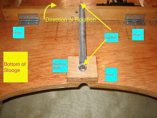
The Rule design can be thought of as two arms with the curve part being the fingers. In other words it emulates a “hooman” release. The arms are raised when the release is activated. A spring provides the energy to raise the arms. The two arms are connected to a piece of wood. Two hinges attach the arms to the bottom of the stooge. The spring is attached using lag bolts to the top to the wood holding the arms and to the bottom of the stooge. You will notice a small block of wood on the bottom of the stooge located at the front. This is to give reinforcing and to help with the angle. The following is a partial view of the bottom of the stooge.

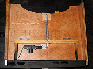
The next photograph shows the complete bottom of the stooge in the armed position.
Next are photos of the angle release bracket and the angle guide.


These are made from aluminum angle.
This is a shot of the top looking down.

The next two shots show the shows the arm in a locked position and unlocked position respectively.


The stooge is controlled with a key fob.
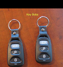
One of the key fobs will be kept with the stooge and will be used to arm the stooge. The second will be attached to the handle and will be used to release the plane.
Flying Lines home page
Back to Musings from the Pits main page
Back to Combat main page
This page was upated Feb. 19, 2021