Scale Matters
Building a vintage kit
By Orin Humphries
September 2021
Photos supplied by the author
Some may remember my A-26 which flew in the Regionals, the American Nats and the Canadian Nats for 22 years and logged 110 flights before being retired in 1992. It now resides in the Oregon Air & Space Museum in Eugene. It placed first most of the time, being beaten a couple of times by Barry Hobkirk’s Spirit of St. Louis and Bob Parker’s Bf 110. One particular loss stands out in my memory to this day, prompting the subject of this article.
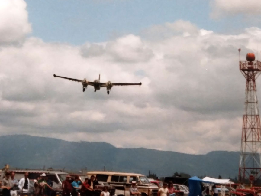
The author's A-26 in flight at the Northwest Regionals at the original Eugene Airport site, which existed from 1968 until 1987.
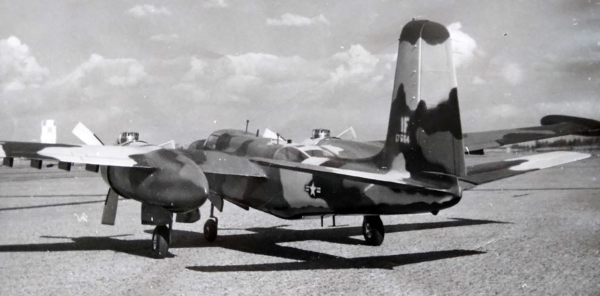
The A-26 at Geiger Field.
I never knew who he was, and only saw him once. It was like he was Clint Eastwood swooping into town, knocking off the bad guy and then riding out, never to be seen again. My A-26 was hard to beat partly because of its twin engines getting extra points. This then-young man did it with a Sterling kit of the PT-17 Stearman. His model could do some aerobatics, overcoming my twin’s edge. “Who was that masked man?”
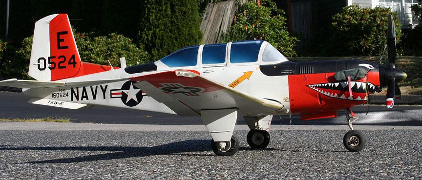
Orin's T-34, flown in Sport/Scale until last winter.
My T-34 in Sport Scale was retired last winter and is going to the OASM this fall. I needed something in that event to replace it. Okay, enter a Sterling kit of the Stearman stage right from ebay. I got it and began, knowing I was in for some extensive modernization of it.
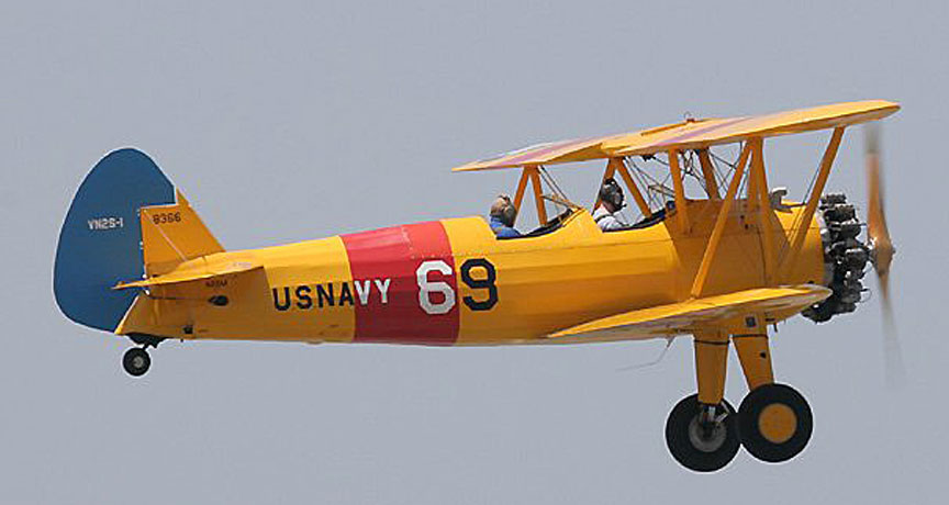
The Mid-Atlantic Air Museum's Stearman in flight.
This is the subject and paint scheme I chose. The kit box is something of an icon in itself.

The kit box.
The bottom line is you have to really want to build an old kit! And I really did plan to use the model’s stunt ability to my advantage in Roseburg this fall.
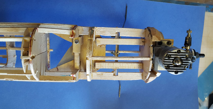
The motor mount.
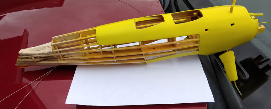
Both this kit, from around 1960, and an earlier project, my Monocoupe from the 1950’s(?), had veritable logs for motor mounts. The 'Coupe’s rectangular mounts reached all the way to the rear cabin wall and were shortened up to the back of the tank. The Stearman’s mounts were to reach to the back of the front cockpit and were very broad and deep. I had to redraw every frame to the back of the rear cockpit to do everything I wanted to. The engine seen here is an OS .20FP. FP’s draw more fuel than old engines.
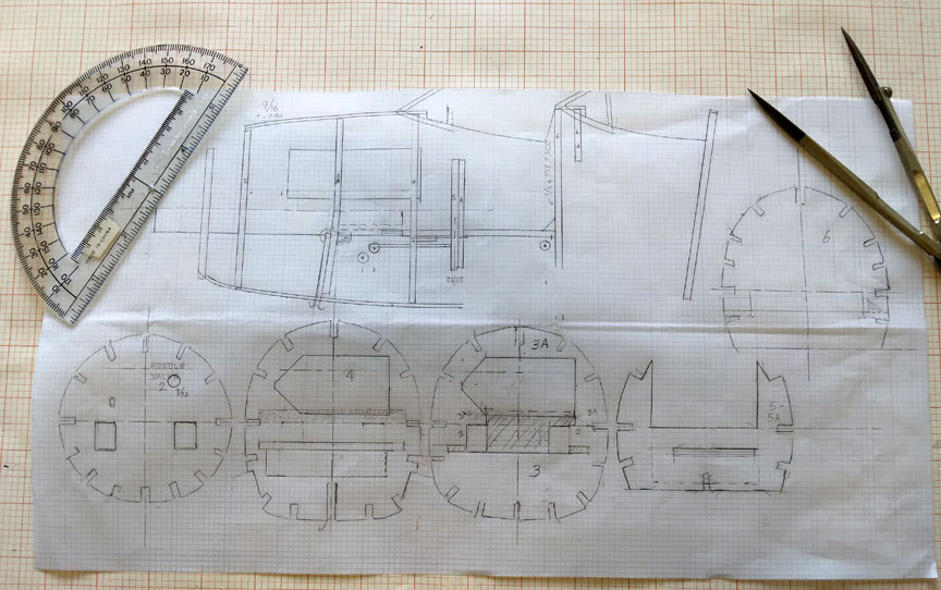
Orin's plan for the front end modifications.
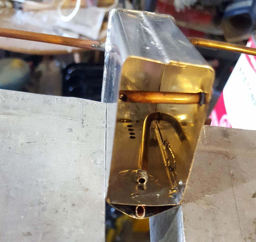
The fuel tank.
I replumbed this tank from Brodak. The tank got the proper baffle as detailed in my last article on tanks.
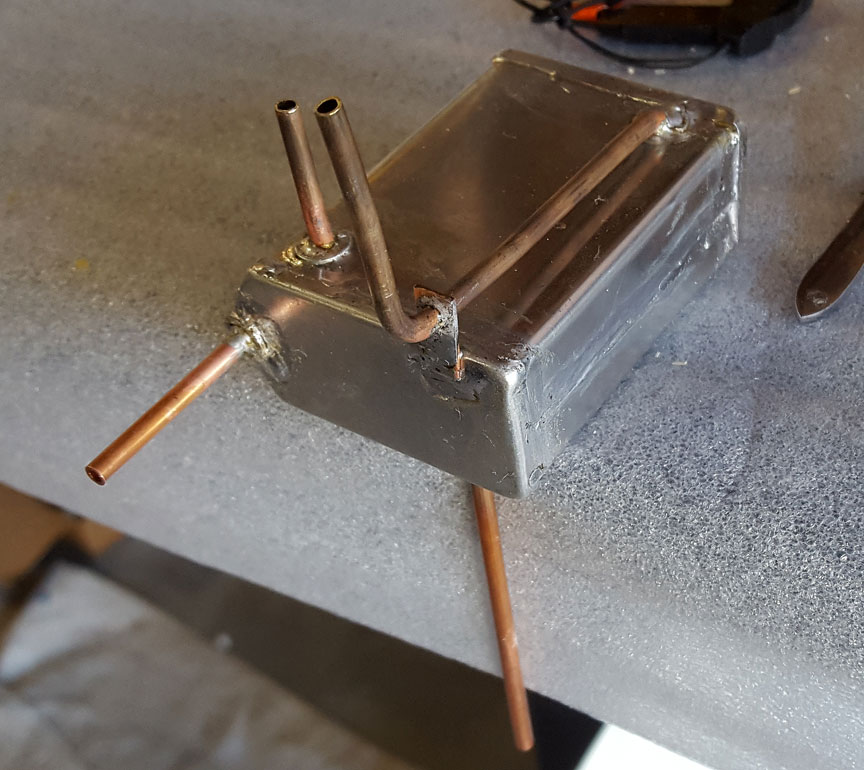
Another look at the modified Brodak tank.
The tank shown is 2.5 ounces and the back end of it reaches aft to the instrument panel in the front cockpit. Flying this model shows that this might not be enough fuel for doing more than two stunt maneuvers, based upon duration in a ground run at full throttle. For this you might need a 3-ounce tank. It would reach into the cockpit ½ inch. Since I aimed this project at Sport Scale this would be no problem for me. But I am stuck with a maybe undersized tank.
I did note in my two first flights that for realism of flight I have to fly at reduced power. Upon landing after 3:45 minutes I still had ½ to 2/3 of an ounce of fuel remaining. This would be enough for one more maneuver for sure with prudent reserve.
The tube on the right top is the uniflow and the long tube on the top left is the service tube. This arrangement is done with the top wing’s LE in mind.
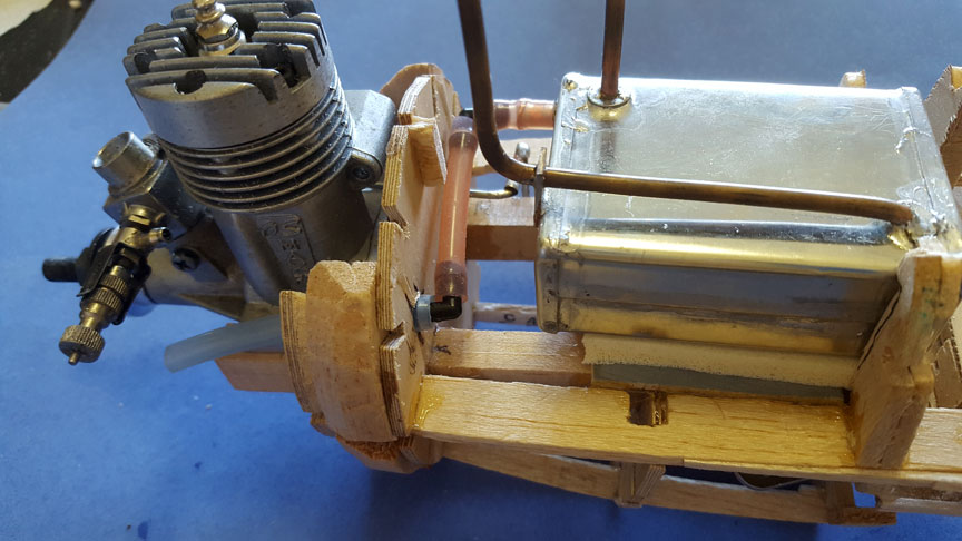
The tank's plumbing.
I used Tees from Fourmost Products. However, on m y first trip to the field I had a problem with one Tee. It turned out that the old fuel filter I pulled out of the box would not pass fuel. I could see through it somewhat, but it was not serviceable. I clamped a forceps onto the fuel line between the filter and the firewall to stabilize the line while I fought the filter off of the tubing. I managed to pull the tube off of the left Tee! So, either put a clamp on that Tee to prevent this or don’t use a Tee at all. I had to cut a hole in a brand new airplane to eliminate the left Tee in the plumbing.
Next is the decision to use a large three-line bellcrank, and this is one small airplane for that beluga! I think I would use the smaller one of I ever did this again. I wanted the smaller sensitivity of the large unit. My new bellcrank platform reached forward to grip the rear ends of the motor mounts and extended to the back of the front cockpit with some of the platform removed to cut the weight.
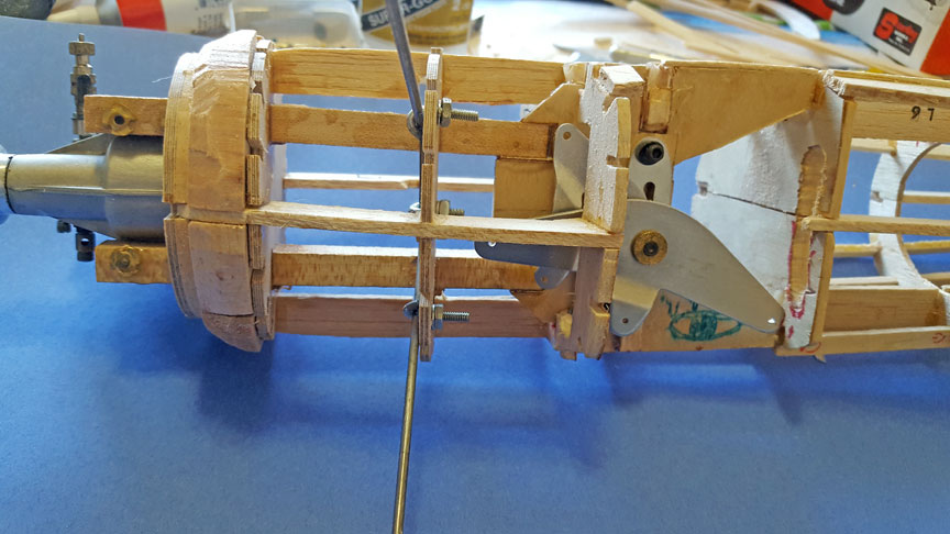
Bellcrank front view.
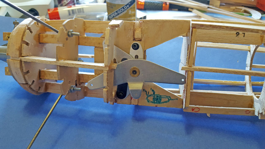
Bellcrank rear view.
I really had to hack out some future wing mounting structure to accommodate this monster bellcrank. My worries about structural strength were for naught; it came together sufficiently in the end. But now, how to get the throttle rod around the tank?
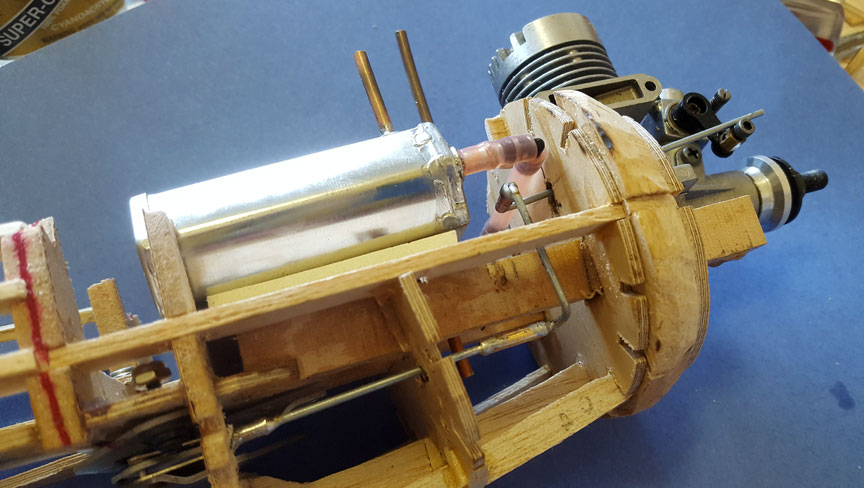
The throttle rod arrangement.
Getting my throttle rod from a suspended bellcrank around the tank in this small of a model required two splices in the line. A one-piece rod was not going to make it through the firewall.

The throttle rod side view.
I did something different with the landing gear. The full-size plane is short-coupled. Models that are short-coupled have difficulty taking off in a wind. They make it less than six feet and the tail comes up, shaving the prop. I moved my axels forward 5/8” by tilting the bottom half of that frame. I located the bottom edge of the half frame 1/8” forward of drawing and the top edge of the half frame 1/8” aft of drawing location. I traded accuracy for serviceability in a contest.
It took some doing, but Orin was able to get close to the proper Cub Yellow color.
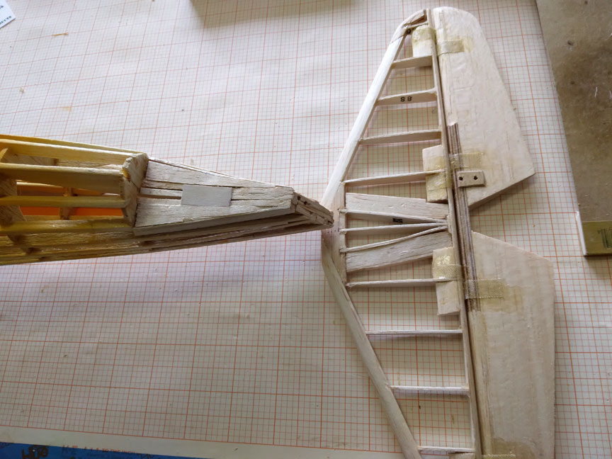
This kit shows its strong parentage in stick and tissue designs. Adapting this kit to piston power they increased the width of the stringers from 1/8” square to 1/8” by 3/16”. The longerons were wider. However, the designer did not address the mounting of the horizontal tail or bottom wing in an engine-bearing model. Those areas were left a la stick and tissue style. I had to add in contact area for the tail so it might tolerate a ground loop better. I also gave the model a solid rudder vice built-up.
The tail platform.
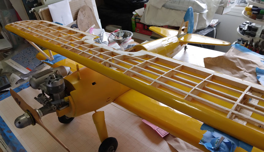
The kit design of the wing reflected the times back then. The spar was a big stick running along the chord plane of the wing. This is of course the worst way to do it. We all know today that the strength has to be out on the surface for the greatest strength to weight ratio and lightest overall weight.
This view shows the wing stringers.
I instead inlaid three 1/8” square stringers top and bottom. Further, the center section was only as wide as the fuselage and I planned to cover the model with Monokote. I needed wood to secure the inboard end of the film so I added wood to the center section on top of the lower wing. The lower surface would take care of itself.
Covering
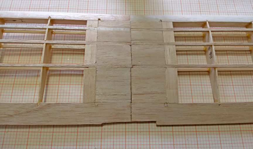
Center section extension to allow Monokote covering.
Seen also in the photo of the whole fuselage above is the tail platform, again. What I don’t have a photo of is the wood borders I wanted to add along four fuselage stringers for anchoring the Monokote. Because of the small nature of the project and the compound tapers in the shapes I used four panels of film to cover the non-sheeted areas.
A problem with regular Monokote in a project this size is that there aren’t extensive widths to absorb wrinkles as the film shrinks. Each lineal inch of film shrinks a finite amount. A project this small cannot tolerate the amount of looseness we commonly have on much larger projects. Super Monokote shrinks better but I didn’t have any. It is said that UltraCote shrinks better than either but I didn’t have any of that either. I am not satisfied with the small wrinkles in the regular Monokote that appear in my Stearman but this is the way it will fly. On to main projects, now.
Colors
Buckle up ... I had some Cub Yellow from Sig for the sheeted forward fuselage areas. On the 1:1 the sheeting is aluminum and the rest is fabric, of course. The paint was darker than the Monokote! I drove an hour or more to get to Spencer Aircraft at Thun Airport in Puyallup. I bought a can of butyrate Cub Yellow from them and drove home. But it matched the Sig Cub Yellow and was darker than the Monokote Cub Yellow. I then tried to order just plain yellow and mix my own to match the film. Guess what? You can’t buy butyrate “Yellow” from Sig or Spencer Aircraft. You can buy Lemon Yellow, Cub Yellow or Cream. Period. Spencer mixes paints but only those formulas approved by the FAA. I bought a can of butyrate White from Spencer who told me that others like myself took it to an auto body shop and had them mix it up. (You add a drop or two of Red to make Yellow turn into Cub Yellow.) I went to an auto paint store and to Home Depot. Neither one would touch this foreign thing, “butyrate”. (EDITOR'S NOTE: Brodak offers quite a few variations of yellow dope, including Cub Yellow and Lemon Yellow. See their color chart.)
I tried mixing Cub Yellow starting with Lemon Yellow. I should have known better, really. Lemon Yellow has a touch of blue in it to make it have its green tinge. As soon as I added red it turned tan. The three primary pigments make brown that way. Duh.
I then resorted to paint fundamentals to get as close as I could to the lighter hue of the Monokote. All paints are partially translucent. We all know that what you put it over affects what the top coat looks like. I first sprayed on White. Over that I sprayed Lemon Yellow. Finally I put a light coat of Cub Yellow over that which indeed lightened up its appearance, I got halfway there.
What to do about this obvious shade difference? I spoke to our mechanic at the Historic Flight Foundation, HFF, Ben Olson. He gave me a great piece of knowledge. He said that you cannot paint butyrate over aluminum; you have to use a different kind of paint. “It is extremely difficult to match that paint and butyrate and over different surfaces,” Ben said. Bingo! For the judges: I am simulating one paint over aluminum and butyrate over fabric. Honest. (Making lemonade, here.)
Dummy Engine
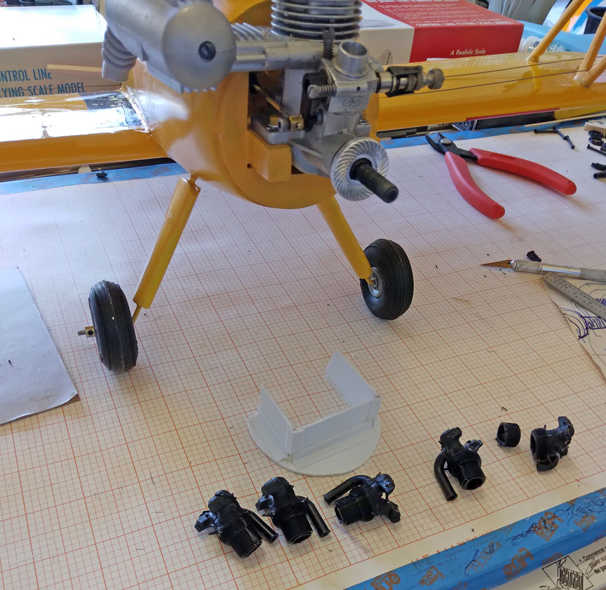
The dummy engine parts.
The engine in the full-size is a Continental R-680 having cylinders that closely resemble those of the larger P&W R-1340. At 1/12 scale the Williams Bros. dummy engine kit for the Wasp R-1340 worked due to the tiny crankcase on the Continental.
My Stearman’s engine diameter is 60% that of the Wasp engine so the Williams. Bros. kit was perfect. Seen are the cylinders and the mount I made for them.
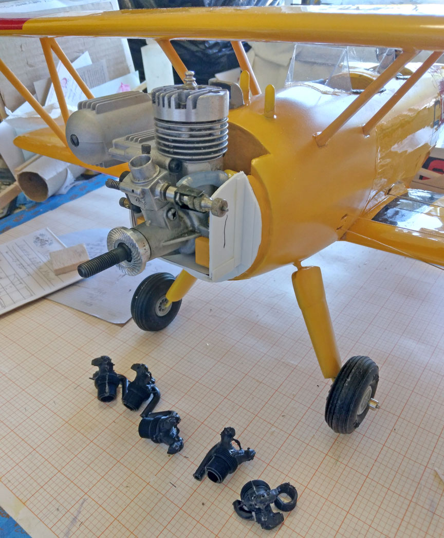
Dummy engine mount installed.
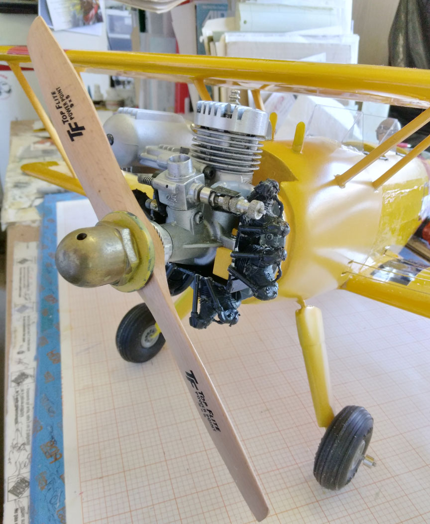
The dummy engine installed.
I cut away portions of the cylinders with a hot knife that hold a #11 blade and looks like a pencil soldering iron. I still haven’t solved how I will get an exhaust collector ring installed.
Hiding the Model Engine

The engine painted.
In 1979 I painted the cylinder of the K&B .40 in my T-34C with flat black K&B Super Poxy to hide it. The paint proved to be heat tolerant and looks great to this day. Here my OS .20FP has been sprayed with Klass Kote gloss black epoxy.
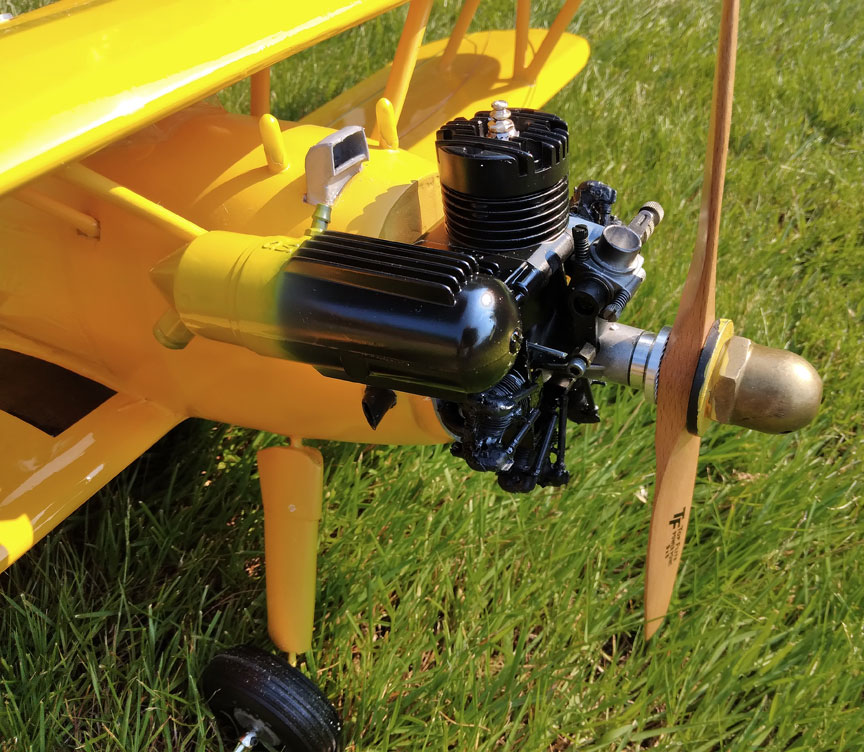
The muffler painted.
With the muffler extending a ways onto a yellow background I decided to try blending it in with the nose. I used a double action airbrush set of the Plastics Community to get the feathered edge to the colors. I thought a diffuse line would be less noticeable than a sharp line.
Leadouts
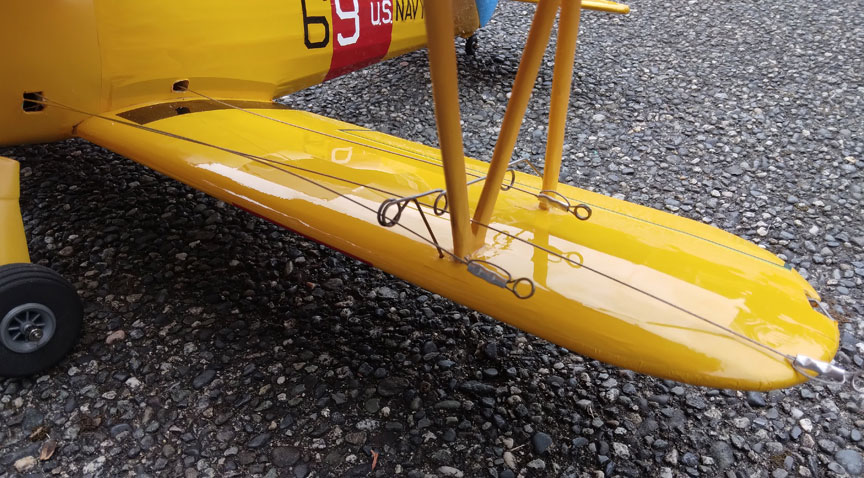
The leadout guide.
I hung the fully equipped model from its leadouts to determine the location of the guide. The guide is made from 0.047” wire. This location gives me the right yaw and very slight roll for proper orientation in flight.
Details
Pilot and panels
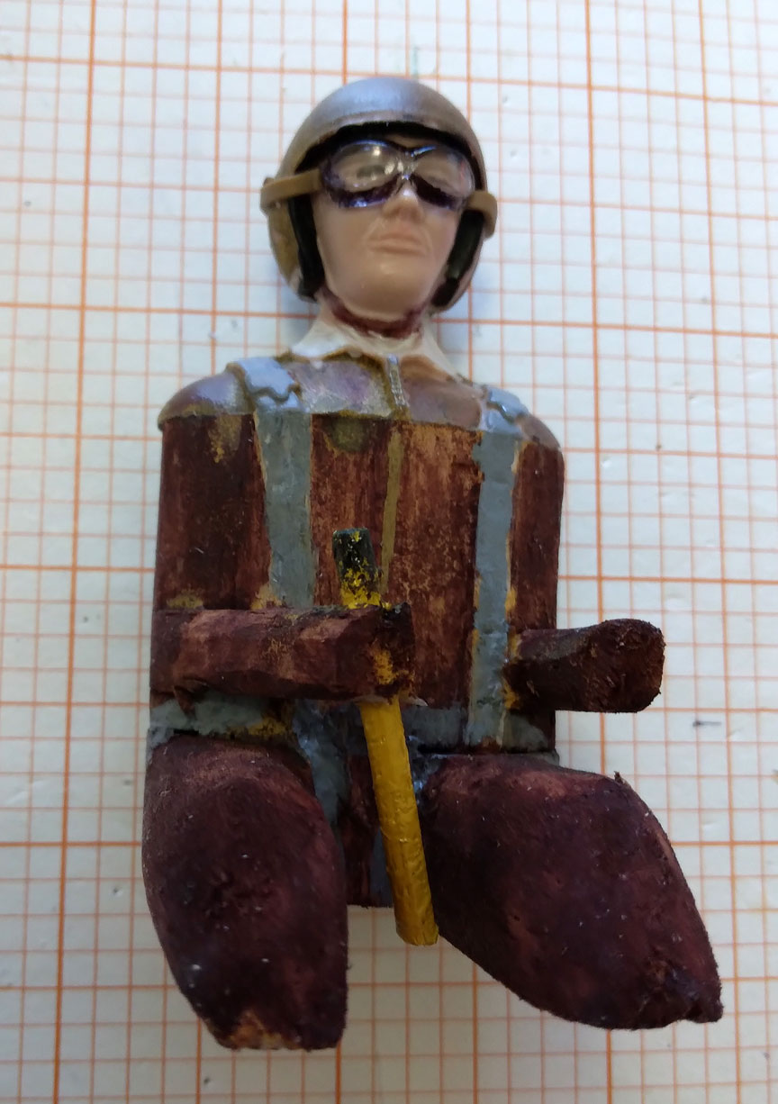
The pilot.
My figure started as a Williams Bros. 1/12 scale bust. He has the wrong helmet for the period but that saves a lot of time trying to make it right. His body is a balsa block and I made channels in it to inset ½” sq. balsa sticks for legs and ¼” sq. stock for arms.
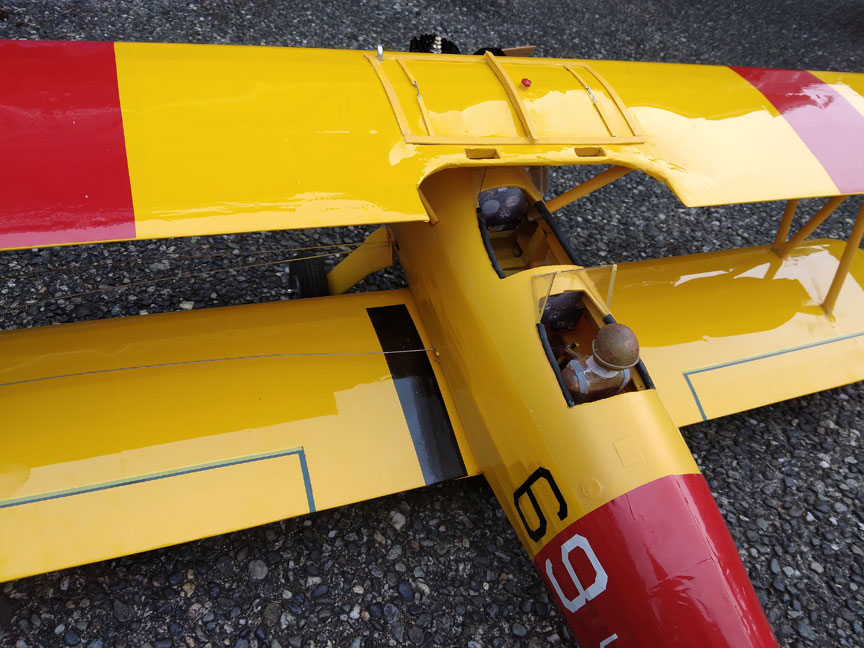
The pilot installed; instrument panels can be seen in this view.
My instrument panels are reduced photos of the panels in the full-size plane at the Middle Atlantic Air Museum from which I got the scale doc photos and markings. They kindly let me download the pictures for this project.
Tank framing
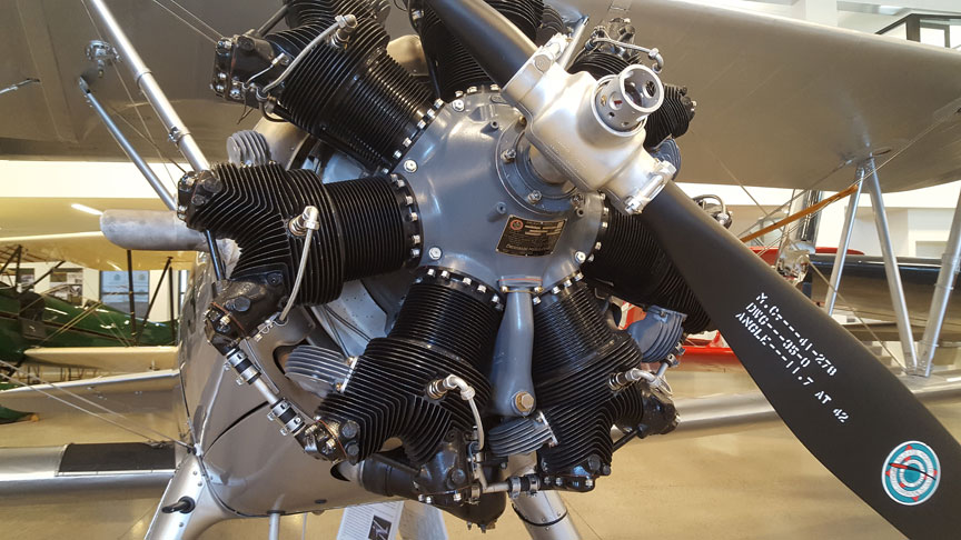
The real engine, as seen at the Historic Flight Foundation museum.
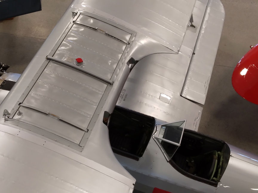
The tank framing.
For my 1:1’s style tank framing I used Styrene strips and shapes from the hobby shop. This was inspired by what the Plastics guys do in Fine Scale Modeler Magazine. Actually, the strips I used for the framing turned out too thick. Once there, though, that’s the way it stays.
Markings
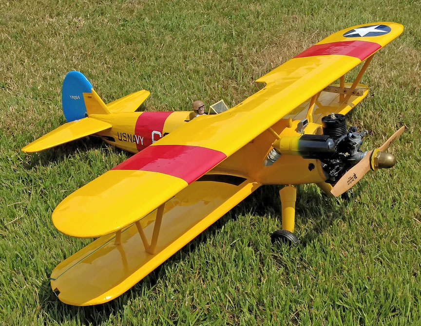
Markings of the finished airplane.
Monokote Trim was used for the markings. The small markings on the vertical tail, seen in the photo below, are subject to being lost from oil and cleaning. The “YN2S-1” on the rudder was cut from Trim strip while wearing a head loupe. The “8366” on the fin was Sharpie Fine Tip which would wash off. To preserve these I covered them with strips of Monokote Clear film. That was a first for me.
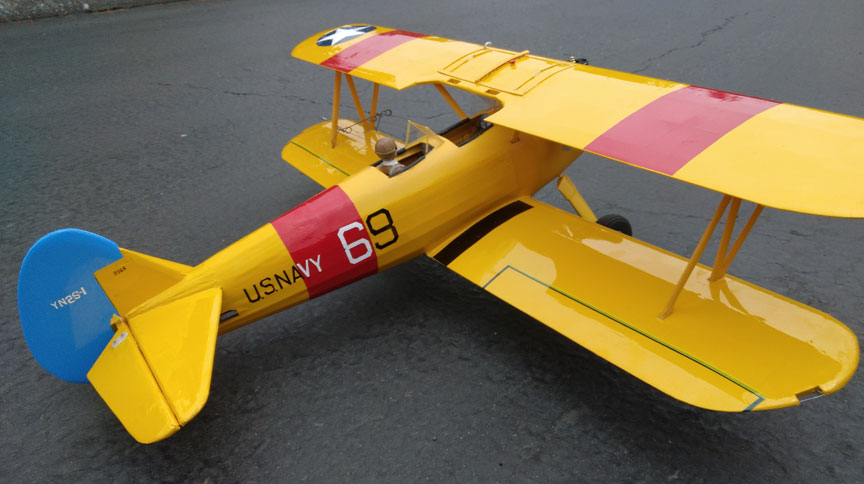
Rear view of the markings.
Conclusion
As you have heard from others who have built vintage kits, you have to really want to build one of these! We have come a long way since then in kit design.
This model came in at 33 ounces. This yields a wing loading of 15 ounces per square foot. That is in the range of many stunters and it gives me hope that this model will fulfill my plan for its being able to do basic stunts.
Potpourri
Main gear alignment
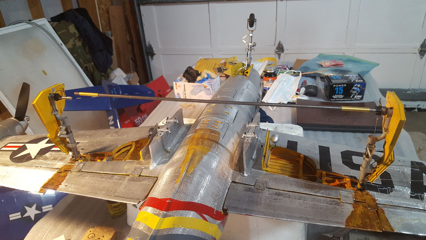
While taxi testing my F-84’s landing gear alignment in my garage I came up with a simple method of aligning my main gear. These legs had Robart Robostruts on them secured by set screws. Mount a piano wire rod between the two axels and connect them with short lengths of brass tubing.
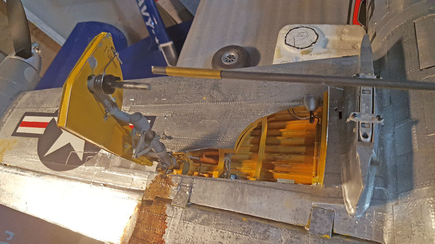
Close and overall views of the F-84 landing gear.
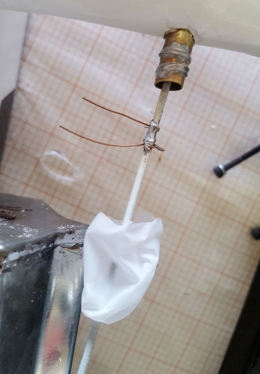
Throttle outlet
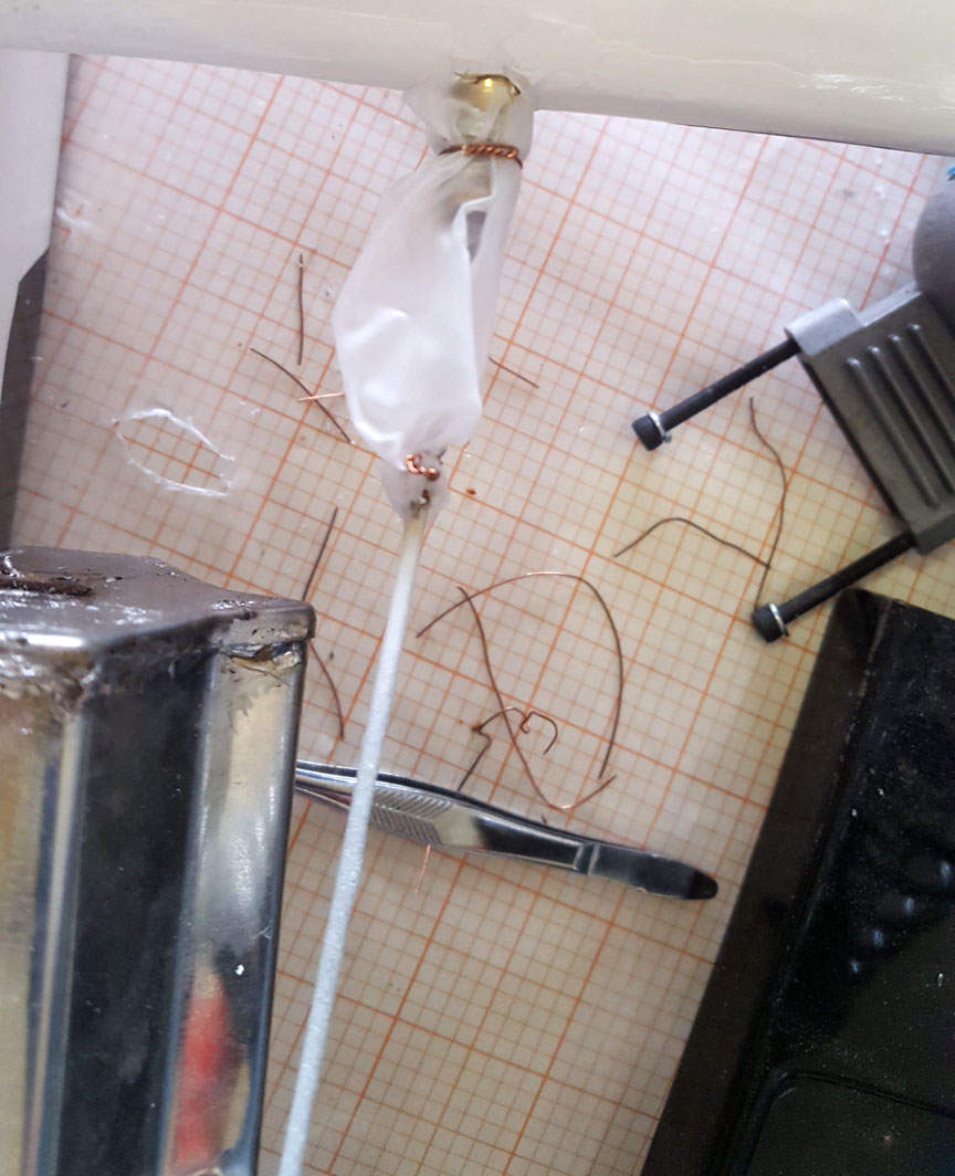
For three-line installations there is an opening in the wing leading edge in many designs. How do you keep oil from getting into the wing through there? I usually use a piece of a small balloon to seal the opening. This time all I had was a baggy fingertip from a rubber glove. I will later replace the fingertip with a smaller balloon piece. This is on a Pathfinder stunter. The throttle rod and brass outlet tube have wire wraps to keep the rubber sleeve in place.
Two views of seaing a throttle outlet to keep out oil.
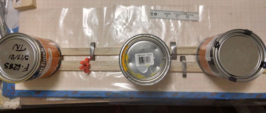
Straightening bent sticks
Most balsa sticks are curved. I spray them with Windex (works better than water) and pair them up with bends opposing each other. They are clamped together and weights placed upon the pairs as they dry. Curves in a second direction need only a second application of the method. It works well.
Modeling and Cancer
California has listed sawdust as a carcinogen. It got me back to my Boeing Lab days. There, I was asked to evaluate a substitute for asbestos as a new heat resistant material. I believed that all cancers were chemical in origin. Examining the molecular structure of asbestos and the new one, I saw that they are very close cousins! They both are made miles deep in the Earth's crust with one being in oceanic crust and the other in continental crust.
But both of them have covalent chemical bonds which meant they are no more soluble in water than granite. There can be no chemical vector for either to cause cancer. I was left with a puzzle. My recommendation was to handle the substitute as if it were asbestos due to their striking similarity.
Years passed before I saw the key to it. Science News published an electron microscope photo of an immune system cell called a macrophage battling an asbestos fiber. The macrophage looked like a soft ball on a curtain rod.
A macrophage's job, being about the third step in the fight against a foreign invader, is to envelope the bad cell, a germ, and destroy it chemically within the macrophage's walls.
But the asbestos fiber is WAY too long for being enveloped, so the macrophage has harpooned itself. The macrophage ruptures, spilling its contents into your fluids. These chemical "tree shredders" then cause cancers via chemical vectors. Finally I understood.
Enter sawdust stage left. The smallest sawdust fibers are physically similar to asbestos fibers and it jumps out then that sawdust can cause cancers.
It follows further that sanding fiberglass poses the same threat as sawdust and asbestos.
Let's be sure to wear masks WHENEVER we sand. We have survived so many slings and barbs getting here; let's not lose it now to what, a hobby?
There; “I have done asbestos I can for you."
Flying Lines home page
Back to Scale Matters column main page
Back to Scale main page
This page was upated Oct. 9, 2021

