![]()
Scale Matters
Tanks and Uniflow
By Orin Humphries
March 2021
Photos by the author
Let me say first that most of the Brodak tanks I use are trouble-free and I like them. This article addresses just a couple of tanks in their broad offering. I offered Brodak a preliminary look at this and they did not respond.
Baffles in stunt tanks have been not understood and misapplied by manufacturers since VECO stopped making tanks. The holes are in the worst of all places and are way too large. The purpose of a baffle is to provide a mini-reservoir for fuel so it cannot escape the pickup end of the feed tube during a sustained maneuver. The location and size of holes in Brodak tank baffles allows fuel to leave the vicinity of the pickup.

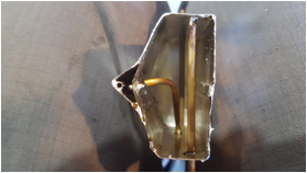
We are looking into the front end of a Brodak-baffled uniflow tank. Note that their baffle holes run the full length of the tank and are present back by the pickup end of where the feed tube is. I fail to see how this could do any baffling. There is also a problem with their uniflow which will be seen in a view from the other end to follow. Now look into the rear end below.
We are looking into the rear end of the tank (the front has been replaced.) Here I have already altered the Brodak uniflow pipe. Originally, the uniflow pipe penetrated the baffle and the end was inside the baffle reservoir not far from the pickup. I have cut the tube on the tank interior side of the baffle and pinched off the remainder that had penetrated the baffle.
To correct the baffle’s hole pattern, I soldered in a bent piece of tank sheet stock that covered off the holes at the rear end of the tank. I left only the front two holes open.
I had recently flown a stock Brodak tank, with the uniflow penetrating the baffle and with full-length large holes in the baffle, and the engined stumbled in a loop and wingover from temporary fuel starvation. With large holes in the baffle at the pickup end of the feed tube the fuel fell away into the interior of the tank. Air bubbles being deposited very near the pickup end were drawn into the feed tube.
Origin
I first became aware of the problem in the later 1970s when I flew my then-new, self-designed profile model of the Fw 190. Its tank was the first offering from Fox after VECO ceased operations and sold tank making to Fox. Early in the flight at the top of a loop in a horizontal eight the engine starved and the model fell, crashing. I was unable to find an external source of the engine failure; there was still a big fuel load in the tank. So I repaired the plane and tried it again. The engine stumbled again similarly resulting in a second crash.
I had at some earlier point gotten into a VECO tank and studied its baffle. There, the holes were at the front of the tank and were small as well as being limited in number. I then understood what goes on in the baffle reservoir. A pocket of fuel is trapped near the pickup end of the feed tube. Fuel could theoretically leave the pocket at the front end and go back into the tank side of the interior, but the pickup end is applying suction to the fuel body that is in the pocket. This suction causes the fuel flow to be sustained in the desired direction. The fuel by the pickup cannot fall back into the tank body, thus allowing air to enter the pickup. Again, with the holes being small and forward, fuel has to obey the suction and move toward the pickup at the rear. This is the key to it all.
When I looked inside the Fox version of the VECO tank I was surprised to find things reversed. The Fox baffle had the holes at the rear of the tank by the pickup! WHAAAT? I could see that the whole purpose of the baffle was blown as a rear location of the holes let the fuel escape the vicinity of the pickup. Why not just cut a piece out of an old screen door and glue that in for a baffle?
Cause
During sustained maneuvering there is a third, transitory force vector on the fuel body. The fuel is trying to move toward the interior of the tank as the plane slows from high angle of attack and gravity plays a bigger role. The fuel moves to a sufficient degree that could lead to fuel starvation. With the Fox-revised baffle my 190’s engine starved.
I called the Fox factory at that time with my finding and spoke to the man in charge of tanks. He was very rigid in his belief that the holes had to be where he had them placed. Reasoning wasn’t going to budge him from it and he had the final say on the subject. In time Fox ceased making tanks and it appears that the designs migrated to Brodak somehow. Looking inside the Brodak tanks I find that they have followed a pattern that Fox was using, except that now the holes run full length.
Recently I resurrected my old Ringmaster cum Zero and started casual stunt again. Things were okay until I changed to a newer Brodak tank. The engine was stumbling in wingover pullouts and loops. Looking inside set me down the current path.
Cure
Below you see the VECO-inspired Humphries Mk 2 baffle pattern. The baffle is laying down flat, 90° from how it will be when installed. Note that I am using four 3/32” holes that will be at the front end of the tank, well away from the pickup end of the feed tube.
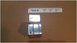
I call this baffle Mk2 as my first version used holes up front that proved to be too large. In the Mk 1 I used five 1/8” holes in a “dice pattern”. Again the engine stumbled in the sustained maneuvers. Reducing the number of holes to four and the size to 3/32” solved the problem. My engine no longer stumbles. Again, with the fuel’s having nowhere else to go other than being drawn into the feed tube and with no air bubbles being injected near the end of it, fuel feeding could not be interrupted. The holes have to be at the front, only. The fuel has to be trapped at the rear.
Over the decades since my Fw 190 I have used the VECO approach in multiple models. The above pattern and location has never failed. Let’s look at some more interior photos.
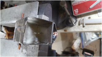
We are seeing my Humphries Mk 2 baffle ready to be soldered. The holes are at the front of the tank and the pickup is seen at the rear.
Now what about a uniflow tube? In the photo below you see that my uniflow tube is installed on the tank interior side of the Baffle. You also will note that I make a habit of moving the top servicing tube to the rear of the tank. This is for tail draggers or any plane that does not sit dead level. Once in a while you want to remove some residual fuel at the end of a session or to verify that that the tank is indeed dry. This rearward location of the service tube eliminates the need to raise the tail with one hand while withdrawing fuel with the other hand. This is not awkward.

Since liquids distribute pressure evenly throughout their body at that level, the atmospheric pressure deposited at the injection end of the uniflow tube appears by the end of the pickup tube as well, via the baffle holes up front.
Two other modeling friends in Washington have noticed the same things mentioned above. I had told them of this coming article. They are Gary Dowler in Spokane and Jim Zevely in Anacortes.
Gary writes, “On the Brodak tanks I have had the same issue. I have bought three of the same model of uniflow tank, had to re-plumb two of them and opened up the third to see why it worked right. All three were plumbed differently. One works regardless of angle/attitude, the others both worked upright, but caused issues when inverted. One causing an engine stall on its first time upside down that forced an inverted landing. Fortunately I was able to I was able to control it much better than I would have a year ago and avoided any real damage.”
Jim said, “I bought two Brodak chicken hopper tanks and they were both plumbed differently. They were the same style, same size and in the same wrappers.”
It is clear that whoever is building these tanks for Brodak does not know what they are doing. It is also apparent that Brodak has not established sufficient, design standards for these matters.
These plumbing faults are causing crashes and extra shop time as we pursue our projects.
“There is no present like the time” – Unknown.
The best tank working tool ever.

This is a small hotplate I got back in the late 1970s from a science equipment company like Fischer Scientific. It can dial up to 700°. I set it at 550°. Note the aluminum foil on the plate itself. This is necessary since the steel of the plate will remove the tin plating from the tank skin. I grasp the tank body with a heavy leather glove and push the tip of a straight slot screwdriver against the lip of the tank back. Easy-peasy. However, to reinstall the tank back later I do not use the hotplate. I put the tank into a vise and use a soldering gun. For me this makes for a much prettier, lighter solder seam.
Potpourri
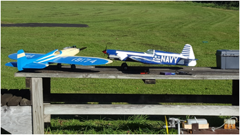
Authentic Scale is so much hard work that this season during COVID I have forayed into sport stunt for relaxation. And I am thinking about doing some Profile Carrier when we get back together. My flying friend, Jeral Godfrey, has gone after Sport Stunt working hard to compete in some of that. We have quite a stables of stunt birds now. He has built old time kits like his Sterling P-40 that he built in 1969, new-construction of a Smoothie, Nobler, and Thunderbird and is bringing out a Detroit from old plans. I have a pair of ARF Noblers with a third one underway being built by a friend for me (I have to have Redundancy!) and I have a Pathfinder coming along soon. Some are shown below. The Smoothie is his from a kit on eBay and the ARF Nobler is mine. The extra white on my Nobler is so I can see it against the conifer background at our circle north of Snohomish, Wash.
The point is that I have built all of the stunt tanks for all of these planes and some others. All of them use my baffle and my uniflow setups and not one of them has had an engine stumble in flight due to a tank problem. Every current Brodak tank that I flew unmodified had a fuel feed problem in sustained maneuvers.
ARF Nobler kits
These kits are out of manufacture but can sometimes be had on eBay. There are serious problems with the foreign-made control hardware and a kit design flaw. The clevises are not all the same inner diameter in the threaded portion nor is this always cylindrical. One such plane was gifted to me be a friend who likes to build and doesn’t have time to fly all that he builds. He builds higher-end houses for a living so building is what spins his props. After my first flight my pitman almost dropped my oily bird when he picked it up. He grabbed at it to keep it from falling and bumped the flaps. That knocked the clevis at the front end of the elevator pushrod loose leaving the flaps at a crazy angle to the elevators. The threads simply slipped in the clevis. Also the two legs of the flap horn and of the elevator horns were not coplanar. Both horns had to be tweaked on a flat surface. The kit and its hardware are made in a foreign country and they are trying, but …
The worst flaw, though, was the kit’s utter lack of a pushrod brace or the use of a carbon fiber pushrod. The plane’s first loops were the size of a small hamlet. (Well…) When I replaced the clevises with American-made ones I installed a carbon fiber pushrod. It corners well, now.
Trim Tool
Working on the trim for my Pathfinder I have marked it up like a real bird called the Pied Avocet. That means giving the model wingtips looking like feathers. The feathers needed thin strips looking like feather quills. I broke out my Monokote SmartStripe tool that I got at a swapmeet. This tool works like a champ, if you haven’t used one, yourself. The dark blue stripes really added to the illusion.
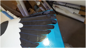

I found on of these tools on eBay so they are around. I bought a replacement wood roller for someday.
Let me leave you with a peek at something to come, with a reminder to fly safely.

Well, it is … air breathing, so… When I fly I practice super-distancing: I stay 60 feet away from everybody! I do. Are you old enough to know where this came from?
“Happy [con]trails to you!”
Flying Lines home page
Back to Scale Matters column main page
Back to Scale main page
This page was upated March 10, 2020