Scale Matters
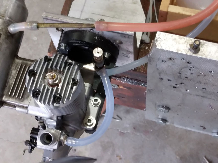
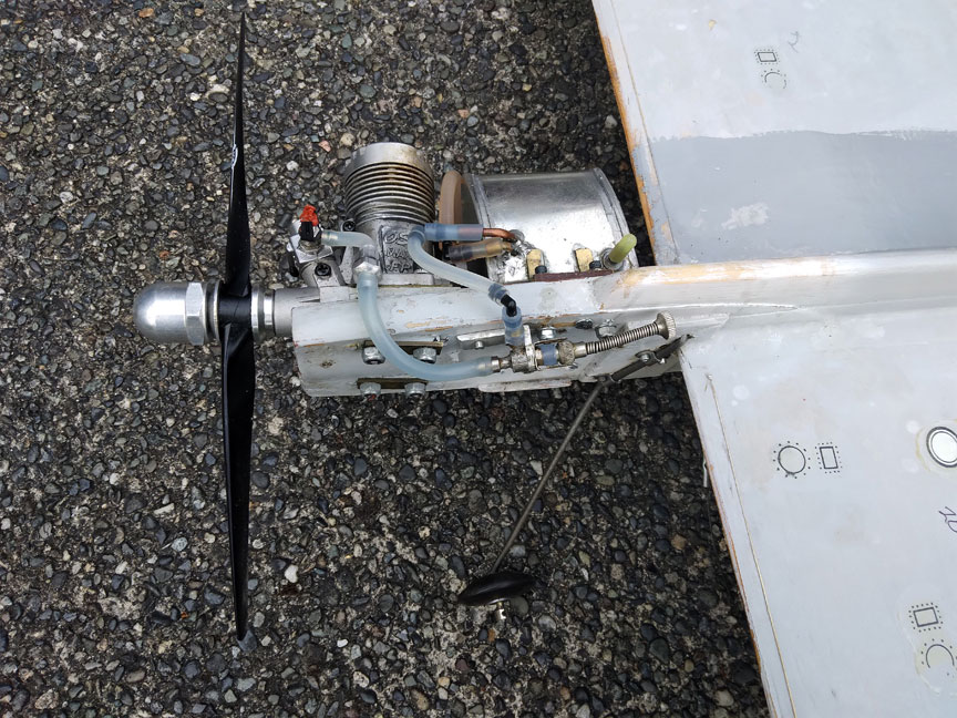
Engine on a test stand with a remote needle valve assembly. All photos by Orin Humphries.
Remote needle valves — and a myth
(+ potpourri)
By Orin Humphries
July 2022
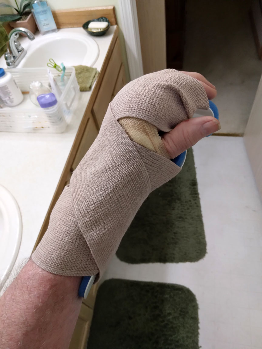
Now that I have your attention, I would like to remind that installing remote needle valves reduces dramatically the number of times your hand gets into an argument with a prop. The prop always uses bigger words and we don’t win these things.
This happened to me recently while using my run-in stand for my new Carrier engine. OS used to make great remote needle valve kits like the unit in the top photo but they are out of manufacture. They changed to a remote unit that has two mounting holes molded into the body. These are plentiful on ebay. So mostly we need to make a bracket like the ones seen below.
There are a few multipurpose OS remote needle brackets for the new needles having molded-in mount screw holes.

The new style OS remote needle valve assembly bracket.
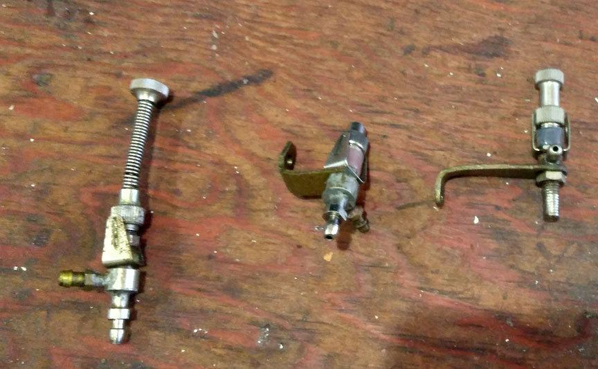
Orin's home-made brackets.
Above you see a couple of home-made brackets that I used.
Over the past three years we North Sound Control Liners have taken at least four hits. Two were minor but two were major. I lost two patches of skin, not just abrading that area, and I got four stitches in the remainder. Jeral’s had a loose skin flap. So, below are some retrofits I have made in this week of June.
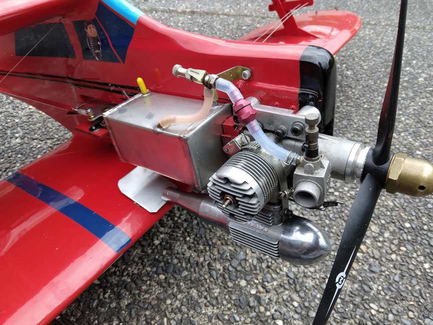
OS needle valve assembly remotely mounted on Orin's home-made bracket. The plane is his profile Beech Staggerwing.
To plug the needle valve body on this engine, I cut off the needle portion. The NV in this newer design has an O-ring on the shaft, sitting in a sleeve, which is the air seal. The body is screwed into the clips until it is secured.
Orin's Seamew Navy Carrier plane with another OS remote NVA on a home-made bracket.
Note how I plugged the factory needle valve body with orange RTV rubber.
One of us besides me up here has embraced the imperative to change to remotes for all future construction. The other pilot has not, leaning on the time saved by not doing this and the weight of our paradigm.
Inverted Engines Revisited
At the Regionals this year we saw the Stunt community for those having inverted engines following their historical paradigm of having the pitman hold the plane inverted for the pilot. In North Sound we never have to do this and we get quick starts right side up. In a couple of previous articles I have shared the strategy I developed many years ago for inverted engines from my Scale experiences.
NEVER have the glow plug in the engine unless you are ready to flip the prop. This prevents engine oil from draining down and flooding the plug. As soon as the plane is back in the pits during a contest the plug comes out. In storage especially, the plug is OUT.
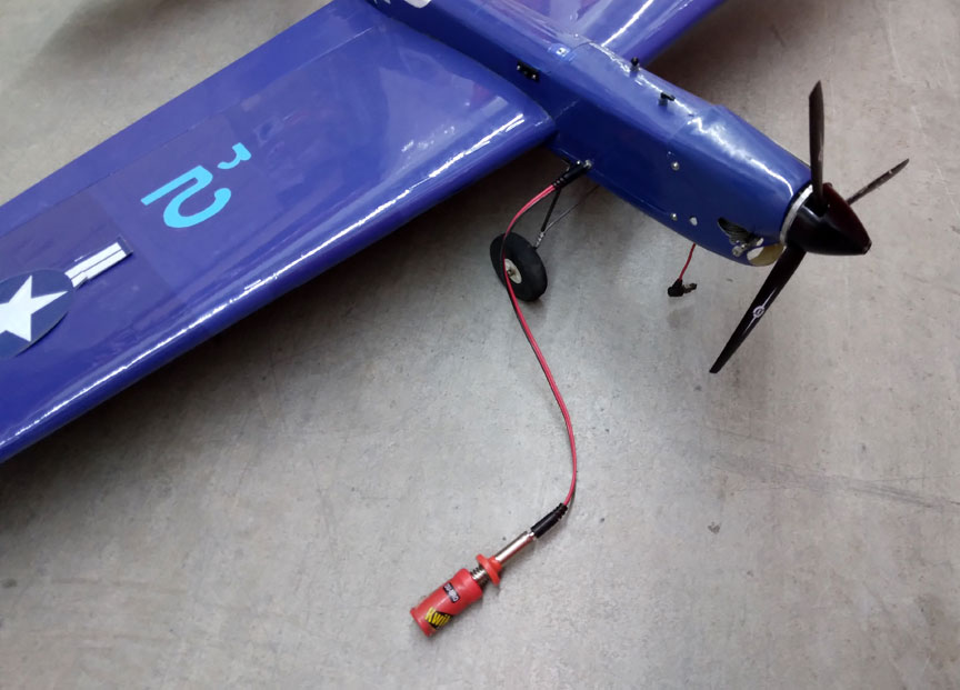
Glow plug hard to reach with the battery clip? Use a remote connection.
Hangar 9 sells these remote glow harnesses. I put one in my T-34 which had an inverted engine and got sold on the idea. This one shown is my ARF Nobler. For our inverteds, we have also installed remote glow plug connections. This is the final piece of the solution for starting inverted engines. I had one style in my T-34C which is now ensconced in the Oregon Air & Space Museum at the Eugene Airport. (They also got my famous Super Corsair which held the Class 2 Carrier record by a Northwest resident for over 27 years altogether.) See Northwest Records.
This Nobler has a radio throttle and a TX mounted on the handle. I don’t do much of the Pattern so I can land when I want to, saving much time and fuel over a season. B&B Hobbies in Spokane, Wash., built the RX for me into a project box I got from Mouser Electronics.
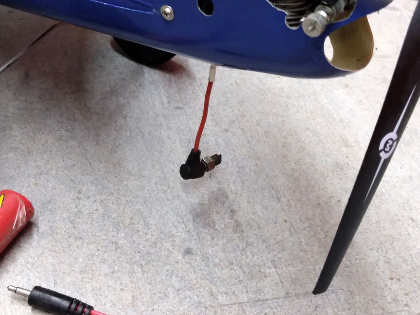
The plug is taken out of the engine between flying sessions.
Note the plug is stored between flying days in the remote connection. If you don’t remove the plug before putting the plane back into the car, you will forget it at home and the plug will be oil-fouled for the next flying session.
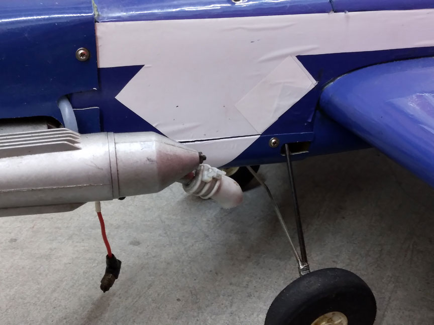
DuBro exhaust duct redirects the exhaust flow.
These duBro exhaust ducts cut the cleanup time by a large amount. I cut mine to direct the oil straight down.
Torque roll
My Berkeley Stearman found a limit no one sees coming, I think. The span is 32” and the leadout guide was mounted on the wing struts. The guide was 10-1/2” from the fuselage center line. For comparison, planes like the Ringmaster have the guide around 20” from the center line. That approximately 20” is sufficient to overcome the engine’s torque from spinning the prop.
I mounted an OS .25 FP on my Stearman which has extra power owing to that line’s triple intake bypass construction. The plane put up five successful flights with a 9x6 on it. I wanted to be able to do a wingover and an inside loop, but the 9x6 prop didn’t delivered enough power for maneuvers. I cut the pitch from a 9x6 to a 9x4 for the huge increase in delivered power at 2,500 more rpm. Upon takeoff the plane rolled in on me and was unrecoverable.
My first guess was that a wheel had caught an edge of our tarpaper runway. Since I had chosen to mount the top wing with balsa struts instead of something stronger, damage was somewhat limited. After repairs upon takeoff the plane rolled in on me again! This time the tarpaper could not be the culprit.
I guessed that engine torque was the cause of the inboard rolls. I changed the prop to a 9x5 for less power and torque. I removed the leadout guide from the struts and installed an extended guide with a provision to remove it for static points. The new guide was 18” from the center line, in the Ringmaster ballpark.
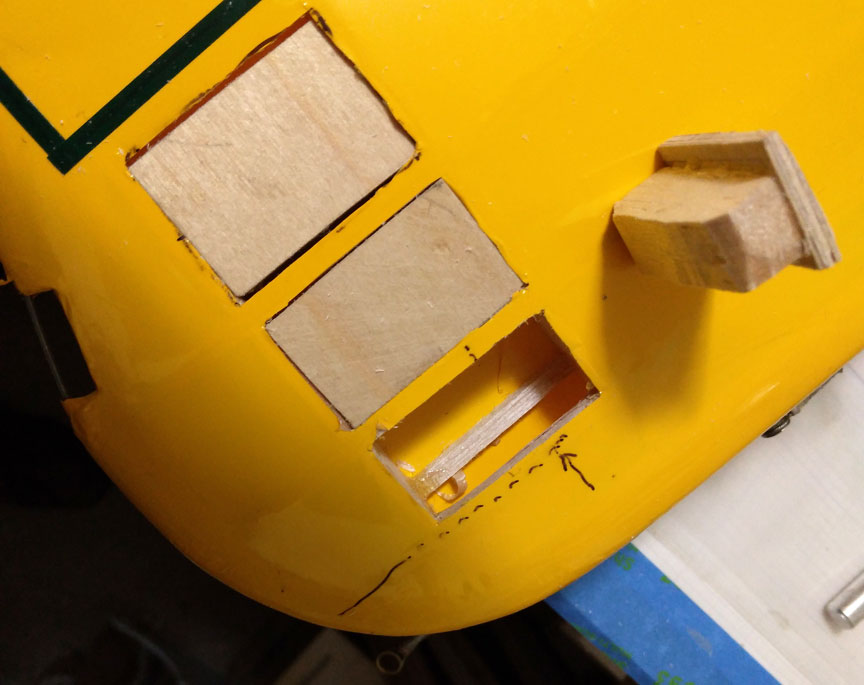
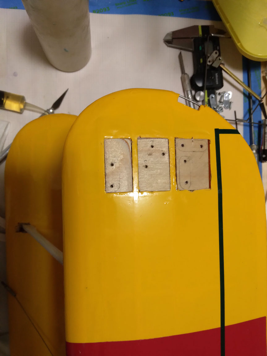
Mounting for the guide block; guide mount pads shown at right.
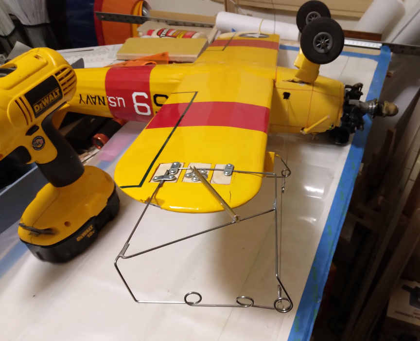
Removable guide installed.
Note how the guide extends beyond the wingtip to gain anti-roll moment.
For the third attempt to regain controlled flight via my new guide and up-pitched prop, the takeoff roll was light on the line tension but I got off and flew. I noted that the plane was unexpectedly rolled a bit toward me in flight, saying that there was something wrong with the mounting of my new guide. I decided to cut the flight short and land. On my approach a gust caught the plane and it rolled in and crashed for a third straight time.
The fault in mounting the new guide lay in the fact that it was mounted to the bottom of the wingtip where the slope is upward. The guide wound up higher relative to the vertical location of the CG. This produced the weak line tension. This was a fundamental limit. There is a relationship between our engines’ rpm/torque and the necessary leadout guide distance from the centerline. What I had blundered into with this vintage kit is a fundamental limit for minimum leadout guide distance from the fuselage center line. This depends upon engine size and RPM. Small speed planes have guide lengths commensurate with the lower torques of the engines thereon.
Dissection: These vintage kits were developed for the world of the 1950s.
- The engines back then had only a single intake bypass which put them at lower power levels compared with our modern triple bypass engines.
- The pilots back then had unlimited access to paved circles. Their wheels were small.
- Today’s pilots mostly have to fly from grass fields, save for a lucky few. Our wheels mostly must be larger to prevent ground loops, hence, today’s larger models.
Having had my fill of repairing this small model, I prepared it for donation to the OA&SM at the Eugene Airport and delivered it on my way to the 2022 Regionals. I began construction of a larger plans Stearman with a 45” span and a Tigre .45. It will have 3” wheels. Its guide will be on the tip vs. the struts and will be properly located, vertical-wise.
Flying Fields
My flying friend, Jeral Godfrey of Mukilteo, Wash., and I went to the Chehalis Airport to fly on that paved pad via the courtesy of the director, Brandon Rakes. That is a 120-mile one-way drive south through Seattle, etc., for us. It is a great surface, but it is only wide enough for 75% of a C-Class circle. This is fine for 95% of the C/L airplanes flying today, but it is too narrow for Scale planes. We need to taxi on a full circle for maximum points in our ground game.
There are NO paved circles for control-line in the entire state of Washington.
The next closer paved circle is the one at Delta Pak in Portland, Ore., a 200 mile one way journey. That circle is very highly appreciated, but 70% of its blacktop surface set a record for the most badly eroded surface I have ever seen! The exposed rocks are near the size of 1/2A wheels. A fraction of the circle was more recently resurfaced and is smooth, but the rest bounces around even C-Class models.
After Delta Park is the airport at Salem, Ore. Its surface had the worst cracks I have experienced. These cracks were filled with tar at great expense by the modelers, but today the tar only forms a U-shaped lining for the larger cracks. Having said that, I flew my F-84 on it one time after first taxiing a full circle to test out the surface. To my pleasant surprise, my airplane could not tell me where any of those cracks were, so …
The next nearest paved surface for us is a parking lot in the Spokane Valley, Wash., 320 miles one way. Oregon pilots don’t know how lucky they are.
The Myth
After publishing on the use of lower-pitch props last winter I have been struggling to find a good way to get through the lifelong mindset of modelers that 6-pitch props are the best for most of us and that the 6-pitch is faster. WRONG! What do I need to say to combat the Power of Paradigm?
The key started to jell two weeks before the 2022 Regionals. Then, at the Regionals a very long and dear friend asked me for some guidance if he ever got serious about adding Scale to his range. One of the things I passed along was to de-pitch the prop to be used. He confidently and quietly opined that the 6-pitch would be faster. BINGO!
The things to say popped into laser focus for me. Hence, we come to this portion, the main purpose of the article. Let’s look at the facts that have not been in focus for most modelers. (The fliers in Speed, Racing and Combat are excepted here, as I know nothing of their worlds.)
FACTS for full-size (1:1)
- This is for fixed pitch 1:1 airplanes.
- The max sustained power output cannot vary due to thermal and stress limits.
- The propeller RPM will not vary with prop changes more than about +/- 200 rpm.
FACTS for model engines
- The power will vary with different RPM.
- The RPM at lean mixture will be vastly different.
- The RPM with lower pitch props can increase by as much as 150%.
Modelers make a fundamental mistake of assuming the use of a prop with lower pitch will also have the engine running at the same old rpm as with a 6-pitch prop. They are thinking in terms of the 1:1s, not model engines.
Example: My OS .40FP with a 9x5 prop on 35% nitro will turn 16,800 rpm.
Re-read my past article on Sport Planes and Prop Pitches, Dec. 2021. You will find an independent test by Bob Gore of the Tri-Cities.
Let me just run a couple of numbers. I get a 150% RPM /power increase with the above. The advance rate of a 5-pitch prop as compared to a 6-pitch prop theoretically is 5/6 or 83%. Multiplying these two numbers together reveals that we have a net gain of 125% in performance. That means we will be going faster with wore power and pull. You will not recognize your airplane; the difference is stark.
(EDITOR'S NOTE: As hinted by Orin above, prop pitch/diameter selections vary by application. One can only determine the correct prop for a given use by flight testing. What works for straight-ahead speed (Racing, for example) may be completely wrong for maneuvers (Combat, Stunt). Best practice is to try several props and see which one works best for your application.)
90° throttle arm
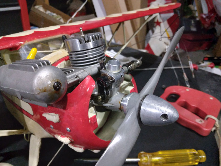
The Berkley Monocoupe.
This is my Berkeley Monocoupe. The ground game in Scale is crucial to having competitive flight scores. You should be standing still upon release. Then you “taxi along the taxiway to the end of the runway.” This should be about 90° of the circle. You pause awaiting clearance. Then you add a little power and start to roll on all three, be that the configuration. After a bit you add a teeny bit of power and raise the nose with a trifle DOWN. After rolling on the mains for a while you lift off and slowly rise to head height.
The landing should be the reverse. You need to settle on the mains and roll for a realistic ways. Then the tail settles and you “taxi to the taxiway” and stop. Taxi along to the pit, about 90° of the arc again. Stop and idle. Then shut the engine down.
To get this low-speed throttling action securely without overcorrecting and shutting down prematurely, you need Vernier control of your low speed throttle. You get this by adjusting the carb arm to be as near to perpendicular to the throttle rod right at idle/stop. This will necessarily move will the carb arm closer to the prop at high speed and different engines will set just how close you can adjust to perfection of this.
Don’t worry about the throttle behavior in the high speed range. Nothing noticeable happens until the throttle barrel reaches down around 50%, right?
North Sound Control Liners
We fly at the SRAC Field between Everett and Monroe, Wash.. On July 7, Jeral G., Jim Z. and myself gathered for another session on our new runway. That is a plastic version of cardboard 8mm thick from TAP Plastics. This is the answer to runway materials. You can walk and kneel on it no sweat.
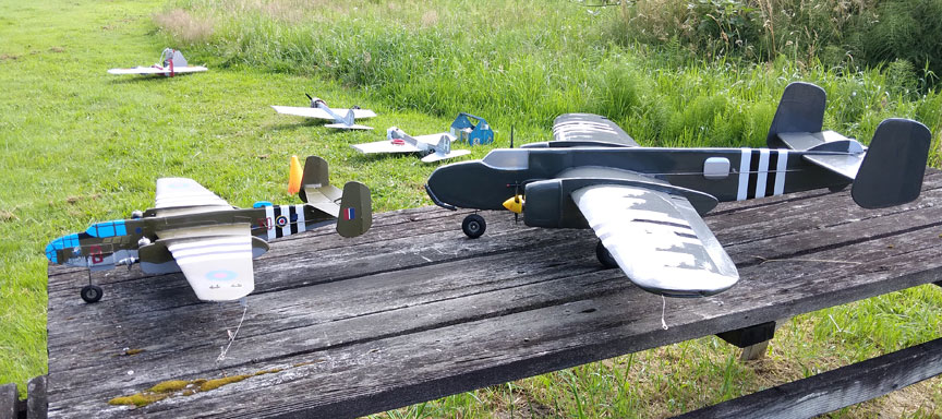
A pair of Profile Scale B-25s.
The small one is my 1/2A twin and the large one is Jim’s own version powered by a pair of OS .25s.
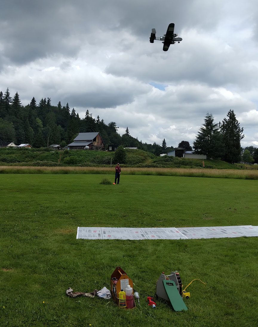
Jim's B-25 in flight over the new runway.
I have to tell you of this flight as two things come out of it. First, his inboard engine died first, unexpectedly, at the end of the flight. First, though, know that Jim is averse to throttle installations and flies his twins on 2-line. Now, everyone who has never flown a twin believes that this situation is an impending spin-in and crash. Not so! I flew my vaunted A-26 Invader for 22 years and had at least three incidents where the inboard died. Never once did there be anything close to a problem. Without getting into the detail, Isaac Newton has our back on this condition. The leadout guide on the wingtip has sufficient control of the plane’s orientation to mean nothing more than “start getting ready to land.”
The plane flew on for another five or so laps before No. 2 quit. And it had enough power for engine-out flight. (It has a wing loading of 16 ounces per square foot.) When the plane reached three feet AGL Jim started a flare. The plane cruised along in ground effect nose high for at least 45° of arc at 15-12 inches off the ground! It was bleeding off energy and was just gorgeous! It settled gently and rolled out. A data point, here is that his CG is at 25% of chord at side-of-body. I have favored more forward CGs in my Scale planes and have not seen much in the way of this scale-like flaring for landing. This ability to flare the landing is more flying points in a contest.
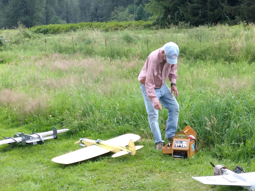
Jeral Godfrey and his Detroit Stunter.
This is Jeral’s recently plans-built vintage bird, the Detroit Stunter of Old. And now:
The First Start of the Day
Engine starting without an electric starter
Our editor, John Thompson, and I have collaborated on this section, and our joint offering follows with John’s contributions in italics.
Competition flyers already know this, but there are minions of sport flyers, some of whom do not. This is for them. Starting a model engine can be a bit mysterious and it is easy to just blame model engines’ nature for not starting.
- Open you needle valve 1/4 turn from where it usually runs. (There is an oil plug in the NV assembly from old fuel that dried. You cannot make enough suction in the venturi by turning the engine over with a starter to move the plug. You need this bigger gap.)
- Put your finger over the venturi and with your hand pull the prop through for three turns. (Note that this does NOT prime the engine sufficiently; it only gets fuel up to it.)
- Move the prop forward, CCW, to be against compression. (This opens the crankshaft port so more prime can actually get inside.)
- Squirt 3-5 drops of fuel into the stack. (This is the actual priming of the engine. Many pilots are afraid of flooding it and don’t put in enough.)
- Flip the prop several times to make sure the engine feels loose and well lubricated.
- Connect to the glow plug. Grip the prop firmly. Turn the prop over slowly; you should feel a “bump,” which indicates that the engine is well primed.
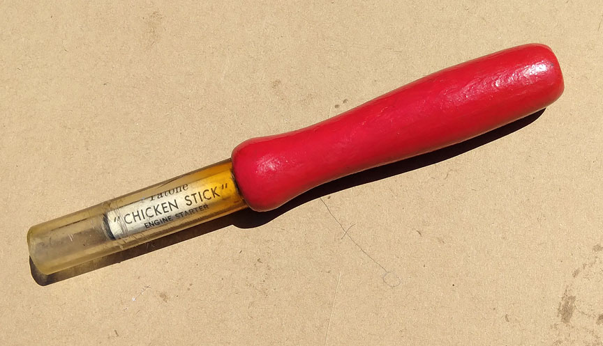
A "chicken stick" to protect fingers when hand-starting. Brodak and Horizon Hobby sell chicken sticks. You can also use a stout glove or a custom-made leather finger protector.
Using you finger to flip the prop is going to get you hit at some time, so we use what we call a “chicken stick.” (The name comes from our being “chicken” to get cut again … )
- If it starts, tune your needle valve to a proper mixture.
Using an electric starter
Older engines, ca. 1970 and earlier usually did not have a paper thin steel washer between the prop drive washer and the front of the crankcase. See the photo below.
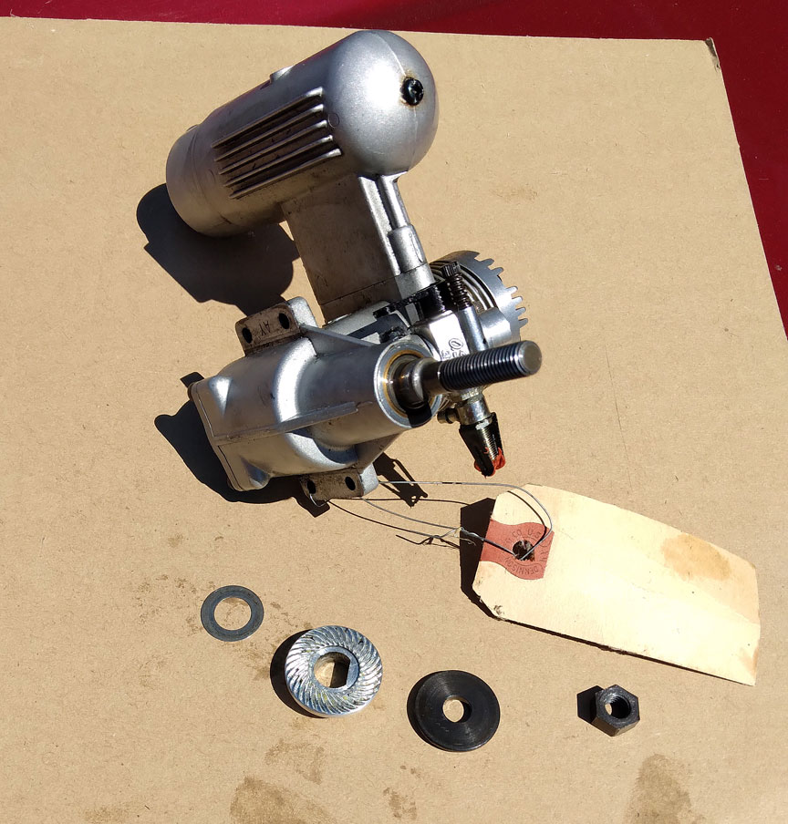
Starting from the right you see the black prop nut, and the black prop washer. Next to the prop washer you see the large, knurled drive washer which sits behind the prop. Last, on the left, you see a modern paper-thin steel washer which should reside between the back of the drive washer and the front of the crankcase. This helps to protect the engine from starter contact.
- Examine your engine. If it does not have the thin steel washer back there proceed as below. Use the priming procedures as above. Instead of the chicken stick, heed the following.
- Back the prop off clockwise against compression. (This gives your starter a needed run at it.)
- Use your starter to spin the prop in short bursts, a couple of seconds at a time. If the engine is properly loose and primed it should start immediately. Avoid prolonged grinding with the starter; this can damage the engine.
If your engine does have the thin steel washer, with the clip OFF the plug, gingerly test this with a little longer starter contact. If you do not feel or hear nothing unusual, you may be able to do what we in North Sound do with our OS FP and FSR style engines. We have never damaged one of these engines, and we use around 10 of them, by leaving the starter on until the engine sets itself ready to start. This might be 7-8 seconds.
- If the engine has not started, stop.
- Move the prop forward, CCW, to be against compression. (This opens the crankshaft port so more prime can actually get inside.)
- Squirt 3-5 drops of fuel into the stack.
- Back the prop off clockwise against compression.
- Again apply the starter.
- Repeat this until it starts. (If it isn’t firing after five to seven seconds of starter use, it will not.)
- Repeat the stack priming, and hit it with the starter for a few seconds.
- (If it starts) Tune your NV for your usual mixture.
The Rest of the Day
You don’t have to do most of the above for all subsequent starts. Usually leaving the NV where it last ran works. If not, open it ¼ turn for the start. You will finger prime the stack for three turns of the prop after this refueling. Back the prop off for the starter. Connect up and hit it.
How many times has a quicky trial at a first starting, skipping the above steps, worked for you?
Breaking-in a new engine
From John:
Model engines are designed and manufactured with differing metallurgy and tolerances. So break-in procedures and running characteristics will vary accordingly.
One of the variables is a fuel’s oil content. All fuels have methanol and some small amount of nitromethane, but the oil content is variable. Oil in most commercial fuels is about 17-22%of the total. Common oil-content blends are all-castor, all-synthetic, or a mix, typically 10%/10%, or 11/11. Some modelers will vary this by adding a little castor to an all-synthetic blend, for example.
Manufacturer’s instructions will give you a starting point for the correct fuel to use.
For example, Brodak recommends an 11/11 oil blend for its engines. OS recommends all-castor.
Here is a good guideline based on experience: First, read the instructions so you know what the manufacturer intended. Then consider this:
Generally speaking, vintage engines such as a Fox .35 Stunt and other engines made pre-1970 will run best on all-castor fuels.
(Let me break in here and add the following: Fox, McCoy, and many other engines of the era had cast iron pistons and steel cylinder liners. The friction in there was so high that these engines required all-castor for cooling. Later on, engines came out with various combinations of aluminum pistons, bronze cylinders that were lined with chrome, ”ABC” engines as they are referred to. These engines have far less internal friction and are almost always happy with blended oil mixes.) Back to John:
The break-in procedures described below will get your engine ready for flight, but the fuel you use in flight may not be the same as your break-in fuel. For example, you might raise the nitro content for more power, and you might vary the oil blend for better consistency.
(Orin, again: Especially in cold weather you will find poor ignition with fuels with 15% nitro and less. Switching to 20% and 25% nitro improves engine starting greatly.) Back to John:
Your experience may vary. If you are having trouble getting the engine run you want, consider trying different fuel blends.
From Orin: John and I both do not like prolonged use of all-castor fuels. We find that this much castor will gum up the cylinder and cause poor engine performance over time.
Breaking-in OS Engines
OS engines are designed and manufactured to different tolerances than many others. The OS engines that are the ABC, etc., style require different fuel if you follow their way. The factory instruction sheet says to use fuels with 100% castor. (Sig sells castor-only fuel.) Per the poop sheet you need only one rich tankful of pure castor fuel and then a few mild runs in flight. “The engine is broken-in.”
Get this: after breaking-in one of these OS engines using all-castor fuel you may not use mixed-oil fuels in that engine. It will get hot quickly and stop. Period. You would have to do what I do as listed below. I have three OS .40FP engines that came to me used. And were said to be broken in. It quickly became clear that they were “broken-in” on all-castor fuel. They quickly got hot and stopped at any usable needle valve setting. I then put them through my routine and they run fine on mixed-oil fuels.
For Mixed-Oil Fuels
This is my break-in procedure. I got it from other factory instruction sheets in decades past. My two flying friends up here, Jeral and Jim, are now using this procedure at my behest, and they are successful with it.
- Use any fuel that has 10% synthetic and 10% castor. Run the engine rich at 8,500 RPM for two minutes.
- Then lean it out to 10,400 RPM or so for 30 seconds and shut it down.
- Let it cool five minutes.
- Repeat this procedure for a total of 21 or so runs.
(I have an infrared temperature gauge, non-contact. I note that at the end of a lean run the cylinder head temperature is typically 285°. When five minutes have passed the temperature will be around 125°. When the engine is finally broken-in the full-lean-run cylinder head will be 175-185°.)
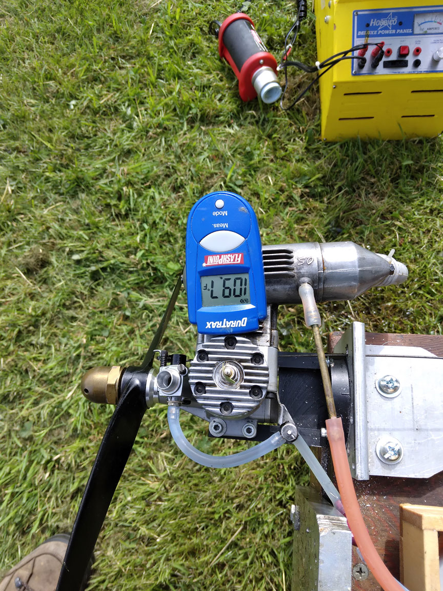
A temperature gauge for engine break-in.
Note during your many runs where your needle valve is reset to get the 8,500 RPM rich portion. That will stay constant until about 18 runs. As the engine gets close to the end of this, you will have to tighten the needle valve to stay down at 8,500 RPM. Through the course of the three final runs you will have to have tightened the NV a total of 180°.
- Your final run will be full lean. Now you must put up about a half hour or so of flights with a slightly rich setting.
You are done and you can use fuel with either castor content. You will likely never wear out this engine if done this way.
Aaahh, the sweet smell of castor at the 49th Regionals AT LAST!
Flying Lines home page
Back to Scale Matters column main page
Back to Scale main page
This page was upated Aug. 3, 2022

