![]()
Scale Matters
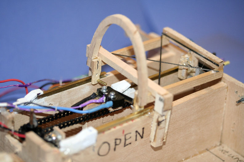
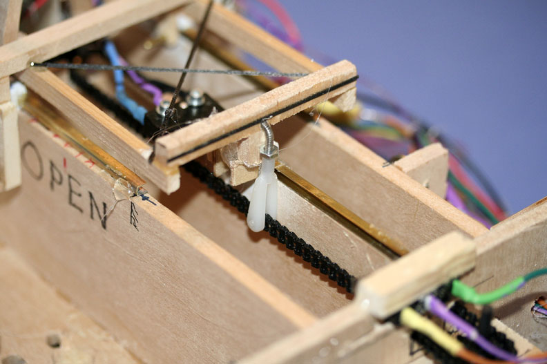
The canopy slider in open position. All photos by Orin Humphries.
Canopy slider, the sequel
By Orin Humphries
October 2015
Part 2
When last we visited this subject, I was investigating a very long term interest, a chain and pulley system for moving a canopy. As you would see in that issue, such a system is a little large for a 1/12 scale project, and the chains seem to stretch for a while. You need a tensioner pulley in the system.
This time, I have completed a test rig with a motor-driven gearbox with a mini-bicycle chain drive. The gears and chain come from Micro-Mark (micromark.com). The gearbox is by Tamiya, product #190. This gearbox comes with integral electric motor, and you can assemble it in a wide variety of gear ratios/speeds. I built up this one in its lowest gear ratio for realistic sliding speed. This tow gearbox/chain actuation. The rig is a veteran!
The tracks as shown in the previous installment are mixed media. The straight runs are brass channel, which is out of manufacture. (I have an excess I can let you have some of.) The down locks are built up from styrene stock from the hobby shop. For my actual installation in the model I will be using tracks I milled out of basswood with my Sherline hobby-sized mill. The frame has three pins made from aluminum tube stock sticking into the rails.
The circuit for this 3v. system comes from a full-sized airplane maintenance manual for a flap system. This is a generic circuit that has been in the books since way before I was born. Use at your own risk. Send me your email and I will send you a copy of it. None of us assume a liability for your use of the circuit.
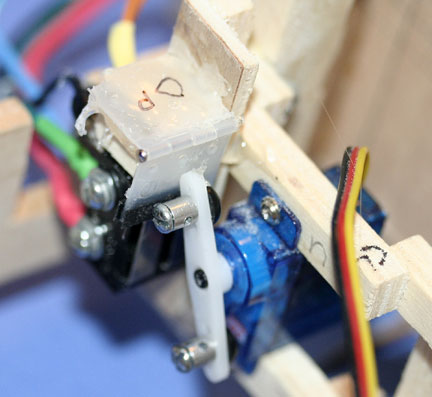
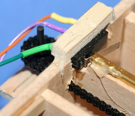
The heart of the circuit is a pair of micro switches mounted side by side as you see in the photos. I got the switches online. Search on “micro switches”. (Get a lifetime supply while you're at it.) There are several companies to choose from and I can't lay hands on the receipt just now. I picked the kind with a little lever for the tang on the canopy frame to hit. It worked out in spades. This little arm on the switch is important. (I did shorten the levers to an eighth of an inch beyond the length of the switch bodies.)
You need to set things up so the tang on the canopy frame that hits the micro switches' levers does so with a mechanical advantage. You want the tang to hit the little lever on a switch at two to three times the distance from the little lever's hinge to the actual button on the switch body. This will cut the tension in the small, plastic bicycle style chain. I don't know what the strength of this chain is, so I am taking it easy on it for long-term service.
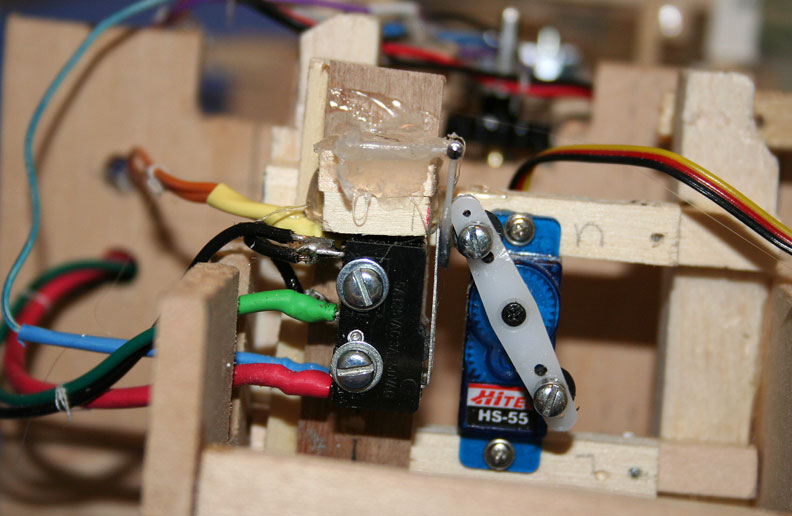
My ganged master switches are operated simultaneously by mounting a nylon elevator hinge over the levers as you can see in the photos. The servo arm hits the hinge blade which operates both master switches at once. If the photo isn't real clear, the pin in the elevator hinge is at the free ends of the little levers on the switch bodies. I also stiffened the elevator hinge's free blade with a narrow strip of carbon fiber stock across the blade on both surfaces of the free blade. That is likely overkill.
The installation of a servo in distributed locations when use of a four-servo tray isn't going to happen gets a teeny bit creative. Attached is the mounting unit for my master switches which had to go in an unused space underneath the rudder pedals.
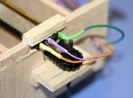
I followed the wire color callouts in the diagram and highly recommend that you do this. My circuit worked the first time because the color coding makes double checking easier. I also religiously included a slow-blow car style fuse in the circuit from Radio Shack (I chose a two amp SB fuse) where it is called out. I don't want a small electric motor shorting its commutater and burning up my F-84! I couldn't find blue and purple wires in a realistic size, so I used white wire that I colored with Sharpies.
In my test rig, I have a push button switch. This will be replaced in my model with a slide switch on the side console in the scale position. Then, what turns off power is the canopy resting at either end of its travel until I turn the panel switch off. I will always park the plane with the canopy open for access to the switch.
Well, if I have forgotten some detail or something is not clear, please feel invited to ask for more info.
This is going to be so cool, sliding the canopy while taxiing! Another thing off my bucket list. &Mac195;
P.S. I have an overstock of brakes for planes with 1/8” piano wire axels. I also have an overstock of three-line bellcranks. If you need some, contact me.
More photos of the F-84E canopy construction

The microswitch closed.
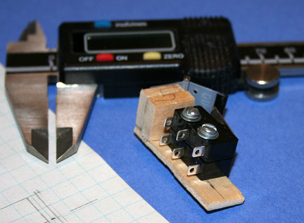
More views of the microswitch, above and below left.

At right, the master switch servo,
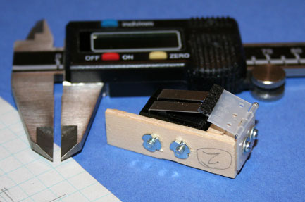
The master switch open.

The master switch closed.
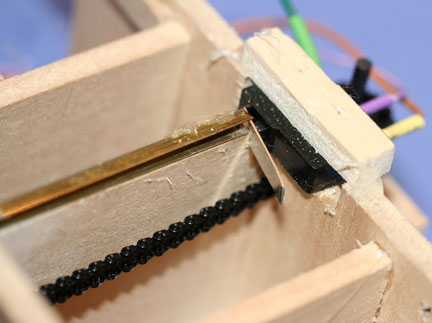
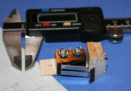
Left, the limit switch open; right, the idler gear.
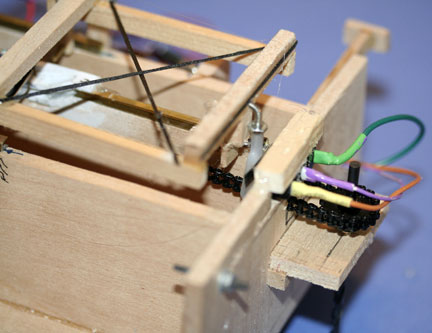
Left, the limit switch open; right, the rider on open stop.
The clevis on the chain.
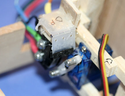
The master switch installed.
Canopy slider installation notes.
Flying Lines home page
Back to Scale Matters column main page
Back to Scale main page
This page was upated Oct. 30, 2015