Scale Matters
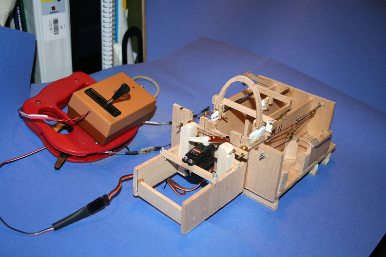
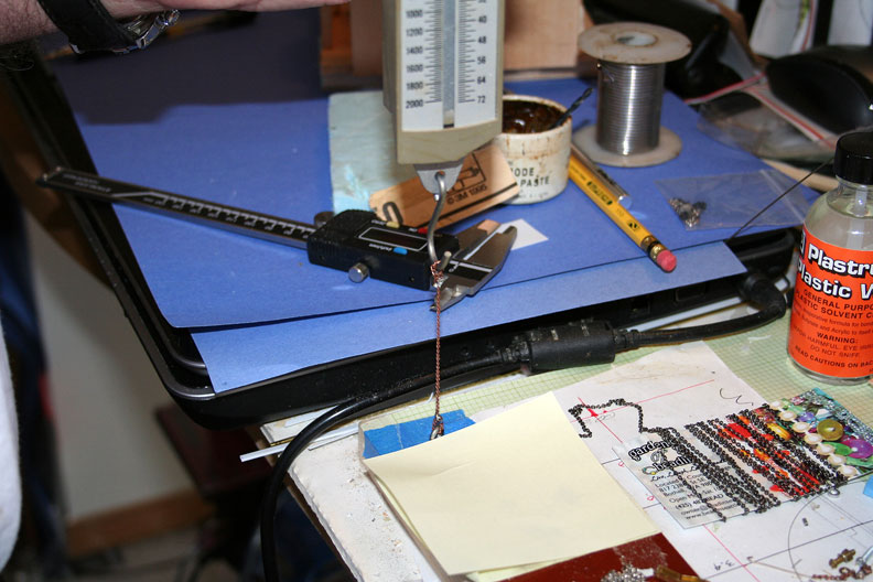
The canopy slider test setup. All photos by Orin Humphries.
Canopy slider
By Orin Humphries
July 2015
Part 1, Pulleys
My F-84 had to await measurements for the bomb racks from a museum back in New York. Since the dive brake, the taxi lights, and the bomb drop cables all go through the same small place, work on that area and those systems stopped. I moved to building a test rig for my proposed canopy slider, the last of the systems to go into this project. The measurements finally came, but I don't want to stop the slider effort in midstream and wind up forgetting some details. The other three systems are pretty much ready for installation.
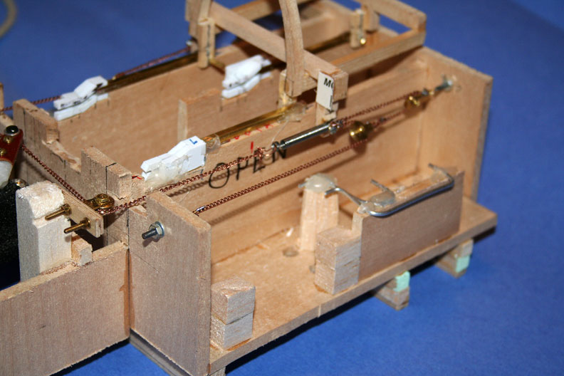
Attached are some photos of the test rig with a simulated canopy frame riding the rails. The system is giving me a challenge just finding hardware for it. In today's world you can't get it off the pegboards at a hobby shop anymore. Bryan Batch at B&B Hobbies in Spokane suggested I try Proctor Enterprises in Oregon for the quarter-inch pulleys. Proctor makes the museum quality kits of WWI biplanes that you see here and there without the covering on them as they are so fully detailed. I bought a lifetime supply of three styles of pulleys from Lou Proctor (made his day!) since he won't be in business forever. (What about you? Are you going to wait to buy pulleys for some project until after he is gone?)
The rails are made from 1/8” brass channel I found in a hobby shop an hour north of my home. It isn't made anymore. I made the ramps and lock channels at the front ends of the three tracks from styrene plastic stock from a local hobby shop. The long, straight portions of the tracks can be made from this if you don't have any brass channel. I mounted the sides of the ramps and lock-downs on a backing made of styrene sheet.
(In the photos, you can still see in this test rig some remnants of the bomb drop testing I did earlier. These are the bent aluminum tubes down on the side, and these are not part of the canopy system.)
For the chains in the system I went to a Ben Franklin craft store and raided their necklace department. I bought some fine (0.070") necklace chain and some ball chain (like in old light socket switches). I rigged up a Third Class Pulley system (from my Physical Science teaching days) and have been discovering the intricacies of such a small system. I searched eBay for sources of tiny chains and received a half dozen products from around the world.
The tiny chains have an inherent strength limit. Each little link is soldered together where the ends of a loop meet. The strength is the stiffness of the tiny wire. At first the arrangement of things was actually stretching the chain. It would be fine when I rigged it, but way slack after one cycle, leaving the canopy frame short of its travel limits at both ends. I fixed the root cause of the stretching, but the system still stops about 3/16" short at either end. (The root cause was using a straight servo output arm. As it swung past center it was stretching the chain 1/2”.) I tried adding tension springs to the chains but with tension in the line the chains still stretched. Currently the springs are just there, unstretched until the system needs them to do so.
My next move was to make another servo arm that gave a longer travel, going from 7/8" long arm to 1.0" long. The chain stretching problem persisted.
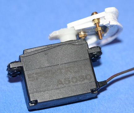
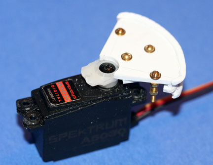
The ideal servo output is a wheel sector with both the OPEN and CLOSE cables coming off it at a constant radius. One cable is paying out and the other is taking in. I built up this sector from styrene stock shapes.
In the confined space available to me in this F-84, I couldn't get a system in there that would simply go full travel, 2.5". I chose a Third Class Pulley system as it multiplies input travel. This is how elevators work when they are not hydraulically moved. The INPUT moves a small distance and the LOAD (the elevator car) moves much farther. The price paid for the gain in travel is that you have to input higher EFFORT force. Now we see why the small chain I am trying is stretching at times.
To keep things simpler, I applied the OPEN and CLOSE cables to only one side each, that is, each has its own different side. I could see that if I weren't careful, the movement of the frame could try to twist the center, rear track rider out of its track. It turns out that if you face the channel for the rear track rider to the left and apply the CLOSE cable on the right hand rail, the rear track rider cannot torque out of its track. You don't need a keeper next to the center rail.
In the end, no kind of small chain available could be kept from stretching a little, and the springs did not cure the problem. There are kinds of installations where a pulley system like this can be made to work reasonably. However, the killer, for my F-84 is that it doesn't look like what is in a fighter.
The next time you read about canopy sliders from me, we will talk about the motor/gearbox and a Rack and Pinion gear system I have settled on. That will be Canopies Part II.
Here's a bonus: Micro Mark sells a small, self-contained vacuum forming outfit. I have just tried mine out for a scale detail in my -84 and it is “OMG, where has this been all my life?” I am using plastic stock taken from commercial products like Swiffer mop pads tubs, etc., and they work marvelously.
Yeah, it's still keeping me outa the tattoo parlors pretty well. Wish they wouldn't have invented that new Geezer Ink™... :-)
More photos of the F-84E canopy construction
Two views of the servo.
The canopy chain pull test rig.
Testing different chains from the craft store.
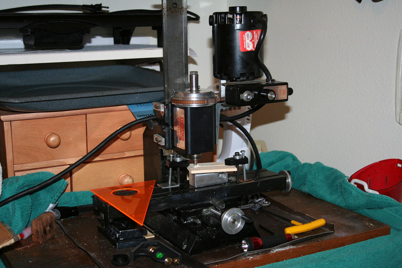
Milling the canopy tracks.
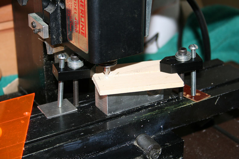
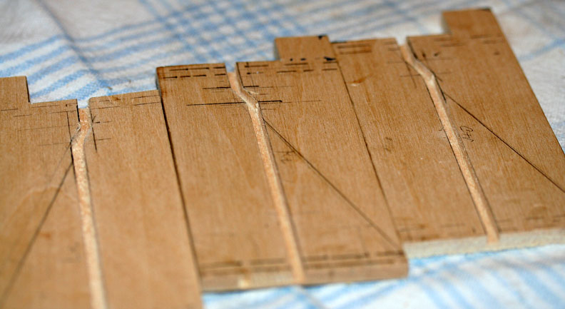
Tracks finished!
See Part 2 of the Canopy Slider article
See article on Orin's F-84E Thunderjet project.
Flying Lines home page
Back to Scale Matters column main page
Back to Scale main page
This page was upated Oct. 29, 2015

