Scale Matters
Of Blackbirds, .049s and the pursuit of knowledge
.049s Part Two
By Orin Humphries
April 2018
Crackup Mystery
Near the end of the last flying season I took my Blackbird to the Arlington, Wash, flying site for its first flight since refurbishment. Earlier, friend Jim Zevely, who lives in Anacortes, Wash., and I had met up there for a day of flying. The new paint jobs on my B-25 and my Blackbird proved to have moved the CGs aft enough to make them almost uncontrollable. After one wild (!) “flight” of the B-25, I chose not to fly the -- it is actually not an SR-71: It is the original, interceptor version, the YF-12A.
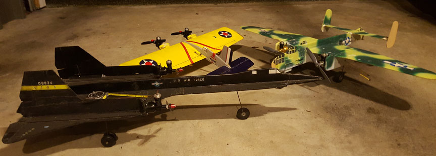
The twin-.049-powered YF-12A is in the foreground. Orin Humphries photo.
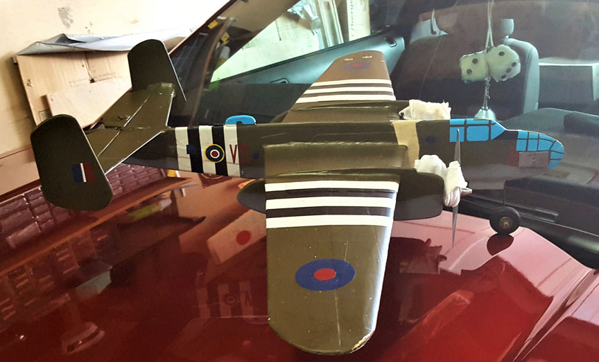
The newly repainted B-25. Orin Humphries photo.
So, at the season’s end I have the YF up with proper CG for its first time since new paint. It was an incredible sight! The bird is so long, and sleek and BLACK out there on the lines; it was just poetry. Three-quarters of the way through the fuel burn, the inboard engine suddenly starved! That has never happened in the decades I have owned this airplane. What followed next was just shocking.
The airplane seemed to almost stop in the air and spin nose toward me on its vertical axis. The lines went slack and I jumped backwards, vainly trying to get control. It was no use. On the second or third complete spin, the lines got caught in the outboard engine and stopped it. The plane then dove at about 45° and struck the ground nose first, breaking the fuselage off the wing over an extended length of the wood above the wing. I just stood in disbelief. The asymmetric thrust of the outboard engine had ruled supreme over the aircraft’s behavior. I had never seen or heard of such an outcome of an engine-out occurrence in a multi-engine configuration. I flew my A-26 for more than two decades having two engine-out flights, and never once even started to lose control. What was with this spin-on-axis thing with my YF?
A Sequence of Events
Why had the No. 1 engine starved? It goes back to my last article, “1/2A Operations.” There, I told of trouble starting my 1/2As. It took 200-250 turns with my electric starter to get them to light off. I came to believe that refueling the tanks somehow flooded the engines. (I will debunk that down below.) On this day of the crash, the No. 2 gave me really hard time lighting off. I got it going, but then the No. 1 wouldn’t light, either. But I got it going after a bit. The No. 2 ran out its supply (shorter in ground run). I got No. 1 going and tweaked, then I shut it down to refuel both.
The outboard one refueled normally and I moved the bulb to the inboard, No. 1. I reasoned that there was still fuel left in the inboard tank so I expected an early refill stop. I saw some fuel coming out of the overflow pipe and stopped squeezing the bulb.
Both engines started normally and off I went, using my stooge. Then late in the flight the above disaster occurred. It became apparent upon reflection that the inboard tank had not, in fact, been full. What I had seen coming out was just slop, not a solid fuel stream. I had believed the tank wouldn’t take much fuel, so -- OK, that explained the starving of No. 1, but why the spin on axis?
Moment Arm
The leadout guide on my A-26, out there on the tip tank, was a good 30 inches from the CG. That was plenty of length, moment arm, for countering asymmetric thrust. The running engine provided one torque, and the slight bend in the lines at the guide, now, provided the opposite torque. Just a little yaw and the torques on the airplane were again in balance. There was still plenty of line tension.
The Blackbird family of airplanes has delta wings, natch. There is no opportunity for a leadout guide to be way out from the CG. My original guide on this bird was at the inboard engine nacelle, a mere 5 inches from the CG. We may conclude (no-brainer) that this can’t counter the torque of the outboard engine if the inboard dies.
Yikes! My B-25 has the same close-in leadout guide setup. Don’t do this on your birds! I have to move the guide out to the tip. This bird is grounded.
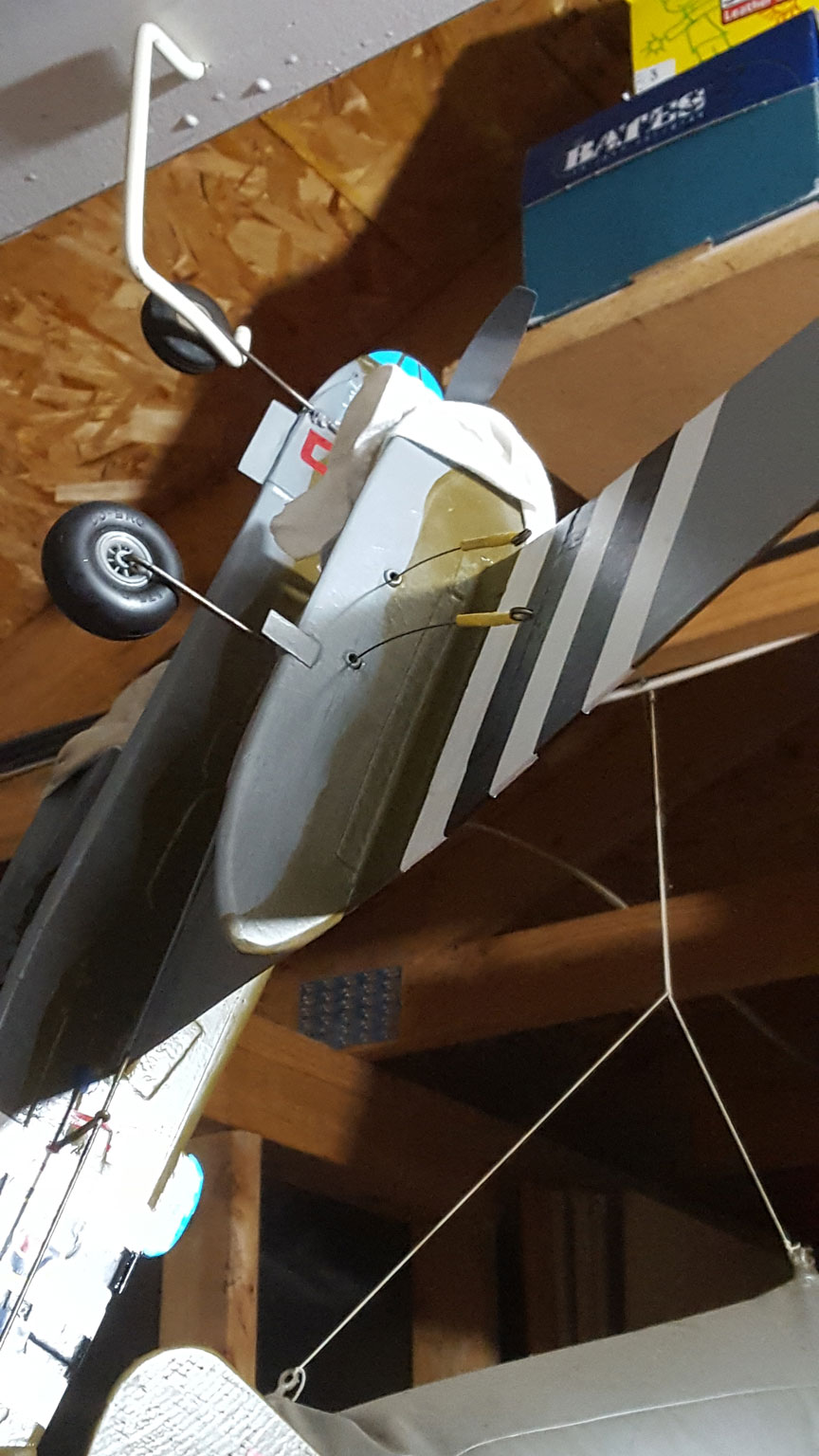
Leadouts on the B-25. Orin Humphries photo.
After a while, I came up with a sanitary way of extending the leadout guide on the Blackbird.
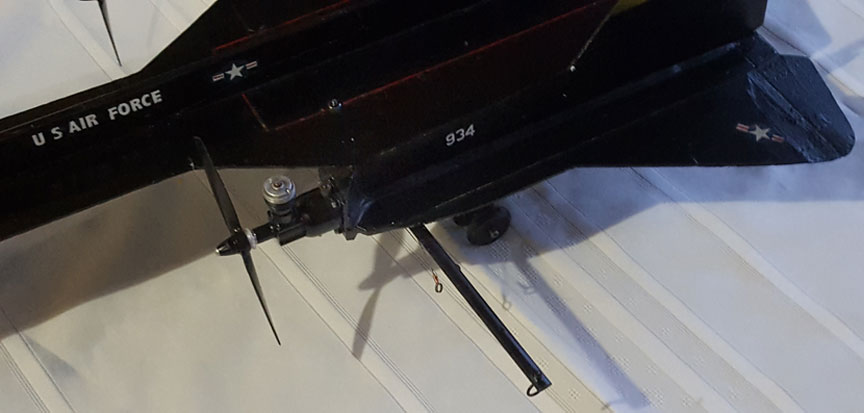
Top view of the leadouts on the Blackbird. Orin Humphries photo.
I chose a piece of airfoiled aluminum tube, 3/8 inch width, for the arm. Under the wing, I added some plywood from the bellcrank to the profile nacelle for mounting the arm. So the tube wouldn’t compress from the mounting screws and actual guide, I filled the ends with five-minute epoxy. I first drilled two tiny holes just inboard of the planned length of epoxy fills to let the air out when I stuffed in the second batch of epoxy in the opposite end, and, before the adding of epoxy, I pushed a small piece of tissue into each end to form dams for the fillings. With the epoxy in place I put tape over the ends of the tube so it wouldn’t sluff out before setting up.
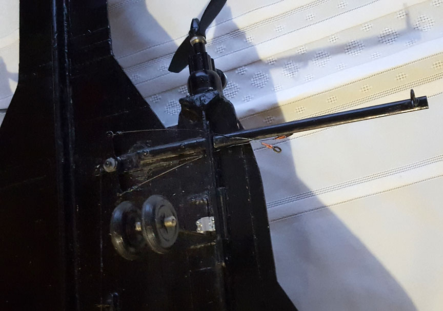
Bottom view of the leadout guide. Orin Humphries photo.
The guide, itself, is formed from a piece of 2-56 threaded control link rod. It has nuts and washers top and bottom on the tube.
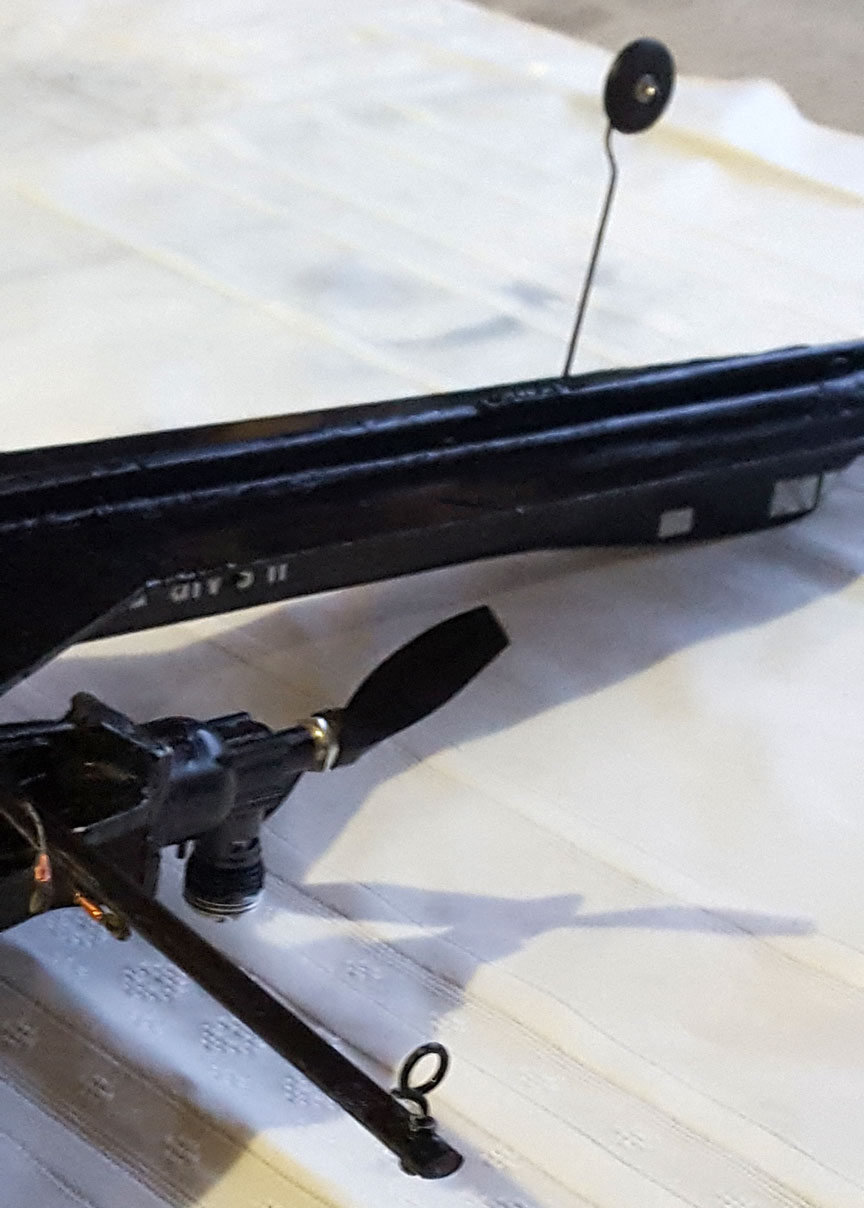
The leadout guide. Orin Humphries photo.
The guide is now 11-1/4 inches out from the CG. Will that give me enough moment arm if I ever again suffer an asym. thrust? There is only one way to find out and I hope I never do! I at least have tried. Yes, the arm looks a little odd. But sometimes we have to make some sacrifice in order to get a serviceable airplane.
On its first flight at Goodman Middle School, Gig Harbor, Wash., following the repair, it landed in higher grass. This bent the aluminum airfoiled boom pretty good. I thought I was going to have to replace it, an outcome I had folded into the design of the boom. At least, the boom had taken all of it and there was no structural damage. At home I tried to straighten the boom just to watch it crack or something. To my great surprise and pleasure, the aluminum in it is not heat treated; it is T-0 aluminum. The boom simply straightened out without further need of work.
B-25 leadout correction
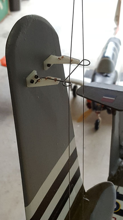
Shown below is the fix to my B-25’s leadout guide. This gives sufficient countering torque for an unwanted inboard engine shutdown. This situation has never happened with this model, but I have to learn from my YF’s experience, which was human error. The bases of the new guide as you see are just control horns with extra holes drilled in them. The wire guide is sewn on with copper serving wire.
The repair on the fuselage resulted from a bad fall in my garage.

Wrong Guesses
They weren’t flooded
Since my .049 article came out I have received several emails from readers. One of them, one of the Old Hands in the Northwest, who said he wished to remain anonymous, here, and I exchanged a lot of ideas. He mentioned at one point that that he opened his needle valves on the 1/2As a half-turn before starting. I have been opening mine a quarter-turn since I got back to flying last year and having the trouble with starting that has been said. Opening the NV that much more made the hard starting routine vanish. They were not flooded.
The Piston Isn’t Cast Iron
This gentleman, above, offered that way back he had satisfactory runs in his .049s with fuel having, according to his recollection, less than 25-30% castor oil. I didn’t know what to say about that. My mixture, stated in my Part 1 .049 article, is one I have arrived at through long, very frustrating trial and error. However, The Wikipedia treatise states that the piston is steel bar stock, not cast iron. That reduces the friction between the piston and the cylinder. The friction is still higher than the friction in an ABC engine. Wikipedia states that Cox recommends a castor content of 18%. That would explain the experience my contact had way back. He was getting by on less than the 25-30% castor I was saying we should have. Note that this is NOT 18% “Oil”; whatever synthetic oil is in there is immaterial. The castor has to be not less than 18%, per Wikipedia. As for myself, I will not run these on less than 20% castor, and I leave experimenting with 18% to the brave reader. My engines do not sag in the second half of the tank with more than 20% castor in the fuel. Again, the synthetic oil makes zero difference with these Cox engines.
Fox Engines and Oil
My correspondent had said that he ran Fox .35s on K&B 100 way back, believed to have 20% castor oil. He said he had no troubles like I did up at the VGMC. Again, up there in the early 1990’s, I tried a Sport Race with a Ringmaster/Zero and a Fox .35. I have no record of what fuel I had used with it. Obviously, it was not Carrier fuel; it must have been some new formulation on the market. The engine got so hot it lagged and could only fly just above stall two feet off the ground. It was the pariah of the event, holding everyone up. I couldn’t land or stop it. Knowing the Foxes had iron pistons and steel liners led me to believe that they had to have 25-30% castor as I said in Part 1. That was all we had in the 1960s.
On February 26 this year, 2018, Ben and I flew for the first ever time at the Goodman Middle School in Gig Harbor on the soccer field. He had asked permission previously. They said they had never had such a request. We flew on a Saturday when no kids were in school. Ben flew his refurbished Cosmic Wind having a Fox 35. I flew my Blackbird for the first time since the crash. Ben’s fuel was a decades-old can of K&B 100. Before we left his garage for the field, we looked at the fuel, which was the same factory color after all these years. It smelled right, so we gave it a go. It flew the Fox .35 just fine with its supposed 20% castor.
What does this result have to say about my assertion that Cox .049s need higher castor? Nothing whatsoever. They do. Let me describe once, again, how I came to that conclusion and you readers can judge for yourselves.
At Arlington Field last year, I flew six different Cox .049s on four airplanes. All of them gave rotten runs on 10/10 oil. They engines sagged randomly during the second half of a tank. Once I surmised that the engines weren’t getting enough cooling from the oil mix, I reasoned that I should add more castor to the commercial fuels. I did so, and the sagging runs abated noticeably. I added more castor until I got smooth, full-power runs for the whole tank. This occurred on all six engines. My castor is not less than 25% by volume. (Who, exactly, thinks it is good to mix fuels by weight these days??? That is unnecessarily complicating a simple job. Use by volume!) Ben just shared with me on my last stint at the museum that there is a website with fuel mixing apps for us. You can figure percentages several ways of your choice. It is NitroRC.com.
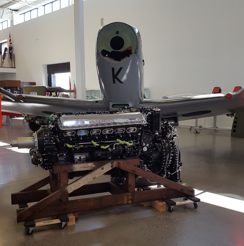
Merlin! Orin Humphries photo.
I don’t know what the exact percentage of castor is for Cox .049s. I believe it is over 20%. Since my two bottles of enhanced fuel for these engines are still half full, I must leave it to some enterprising readers to pin this number down for the rest of us. I am asking someone out there to start at 20% castor and see what happens. If that doesn’t give a consistent run for the whole tank, then bump it to 22% castor. Keep going up by small amounts until you get no more sags. Please let me know what your results are, and I will put your name up in lights in this column. Please don’t keep it to yourself; I gave the world my info freely, and it behooves anyone who has benefited from my information to pass on their contribution. Finally, I have never had one of my Cox .049s flameout while I am using 25-33% nitro. There you have it.
I therefore stand corrected on this new point from Part 1: Foxes don’t need over 20% castor.
The day after flying with Ben at Goodman MS I did some garage runs at my daughter’s house in Gig Harbor which I was house-sitting for her and Jack while they went to San Diego for a weekend. Before, at the field, my Blackbird’s No. 1 engine had been weaker, taching at 17,100 rpm cold, settling to 16,700 warm. My No. 2 stabilized at 17,100 rpm hot. No. 1 had wavered a little as if there were foreign matter somewhere inside.
There was no foreign matter that I could find, but the Mylar reed valve had taken a set. It was bowed toward the crankcase. I reversed the reed to be bowed toward the tank. After this switch, Holy leapin’ lasagnas! It topped, cold, at 18,600 rpm! It warmed to 18,100 rpm. I could have leaned it another 200 rpm, but stayed conservative. I had never seen anything above the 17K’s with these sport engines.
The No. 2 engine had a bowed reed as well, so I reversed that one. When cold it started at 18,200 and stabilized at 17,600. These were with 33% nitro and 6x3 props shortened to 5.5 inches. This was a thousand rpm faster than the previous day at Goodman. I put the stronger engine on my inboard location and decided to check the reeds and this result another day. A check of the weather channel revealed that the air pressure for these runs was anomalously high, at 32.11 inches Hg and the temp had been 41°F.
Two days later I checked the weather and the pressure was 29.91 inches and the temp was 41°F in my garage at home in Lynnwood, Wash. My altitude was maybe 350 feet higher above sea level. The engine now on No.1 position started at 17,900 rpm, stabilizing at 17,500 rpm.The engine now on No. 2 position started at 18,100 rpm and stabilized at 17,600 rpm. So, the 18K rpm I had seen in Gig Harbor had been due to unusually high air pressure, putting more oxygen into the cylinders.
I shortened No. 2’s prop an additional 1/16 inch each blade. It then tached 17,800, varying a few hundred rpm, for a gain of about 200 rpm. I put this engine back on the No. 1 position.
I have found that which way the Mylar reed bows does not make a difference. It will bow toward the low pressure side (crankcase) after one run.
Part 3 to come
All this testing got me into the mood to do a thorough wringing out of the many cylinder designs for the Cox engine line. What difference do we see with the two-slit ports? How do the old Baby Bee engines compare, power-wise? What do we get from the newer sub-piston induction? Tee Dee cylinders? What about the three different materials that you can get reeds in from Cox International? And so forth. I will do these tests with the same prop and fuel on the same day this summer after I make some progress on my -84. “Stay tuned for the exciting answers.”
Arlington
In March, Jeral Godfrey and I flew at the Arlington field. He is a friend from the museums I have volunteered at and a retired Boeing engineer.

Jeral with the XF13C restoration project. Orin Humphries photo.
We met there on a Tuesday when the competition aerobatic pilot practices. For the first time to my knowledge in perhaps decades, we all set up two, count ’em, TWO, flying circles at Arlington! There were we three pilots and four airplanes in the pits.

The pits at Arlington. Orin Humphries photo.
Jeral flew his Me 109 for the first times in a long time. He put only a half tank of fuel aboard, and during the flight he was wandering away from the center cone. I called to him about that, and he sort of waved at me with a dizzy look on his face. After he landed he laid down until the world got back to normal. After his third flight he had acclimated better.
I flew my Blackbird next. My No.2 (on this day) would not lean out, but it was safe to fly. After No. 2 starved, the plane stayed aloft on the inboard and landed normally. It has huge wing area. At home, I found plant matter had covered part of the screen. After that Jeral put up another flight, and then I made the inaugural flight of my new Sterling Monocoupe.

Orin's Monocoupe. Orin Humphries photo.
My ’Coupe is from a late 1940s or early 1950’s Sterling kit. I had paid Jeral to build it for me so I could stay on my F-84. As I am not the BOM, I will enter it in Fun Scale at Roseburg. The ’Coupe’s CG is at 17% and it flew like a dream. I shot a couple of touch and goes and then brought her down. I stayed conservative lest a gust hit it on this first time out.
Oldy
Jeral flies CL, radio control, free flight, and-stick-and tissue FF. His RC club meeting place had an ancient CL model hanging up, which was in really bad shape. The club didn’t want the model. Jeral likes to fix damaged models, so he asked the club if he could restore this old model. It has right-hand leadouts! It seems to be a Curtiss XF13C parasol fighter prototype. It has the motor mount spacing for a .60.
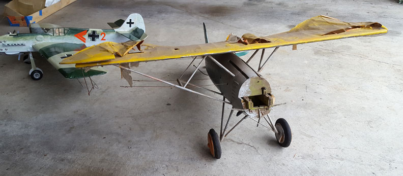
Front view of the XF13C. Orin Humphries photo.
I suggested that he should ask the club, RC guys, if this crucial modeling point of history could be donated to the AMA Museum after restoration
Heat production/cooling ability, an aside
In my first article I speculated that the Wright R-3350 engine had the largest practical volume per cylinder for the cooling fins to handle for mass-produced American full-size engines. I have run some numbers on that and found something else. As you know I give tours in the Historic Flight Foundation museum and I get a lot of questions, so picking up factoids is part of my job.
This started with our mechanic, Ben Olson, telling me that the Wright R-3350 came into being by Wright’s enlarging the R-2600’s crankcase to go from seven cylinders per row to nine. That means they likely used the same cylinders. My calculator tells us that the R-2600 on our B-25D has 185 cubic inches per cylinder. My calculator further notes that 3350 cu.in. divided by 18 is the same 185 cu.in. So, which full-size engine, then, holds the record in America?
The Pratt and Whitney R-2800 on the Corsair and the Jug, etc., has 18 cylinders which comes to 155 cu.in. per cylinder. The Wright R-1820 on the B-17 has 202 cu.in. per cylinder. The P&W R-4360 has 28 cylinders and comes in at the same 155 cu.in. as their R-2800. Surprisingly, the R-4360 has a smaller diameter than the R-2800. Further, Pratt doubled the number of cylinders to build the 4360 (with the cost, weight and complexity) for a horsepower gain of 42%.
And just to cover the range of engines in the museum, the Engineering Landmark R-1340 has 149 cu.in. and the reduced version, the R-985 has 109. The R-1830 on the B-24 and DC-3 has 131.
Thus the largest mass-produced cylinder volume goes to the R-1820. I am not an engine designer, so I cannot speculate on the decisions to go to the R-4360 design.
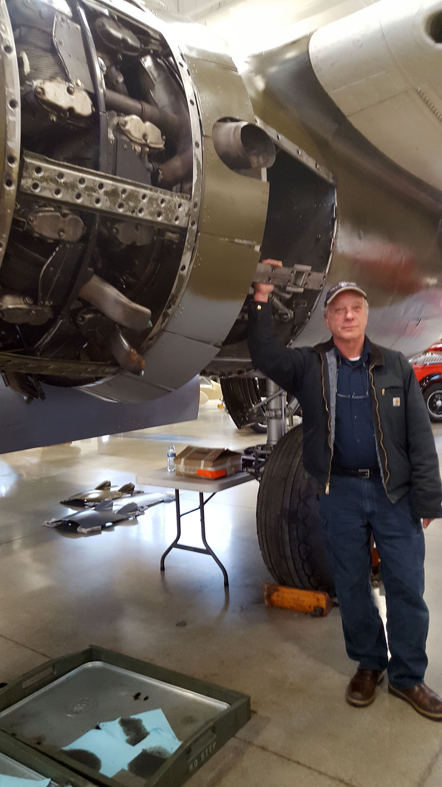
Ben Olson. Orin Humphries photo.
I asked Ben to rate the various engines. This is what he replied:
“The R-1820 seems to be a fine and reliable engine and [was] certainly improved and refined over the years of production, not unlike the Pratt & Whitney R-985, R-1340, and especially the R-2800. These engines also suffered “growing pains.”
“As I see it the R-2600 was produced for warplanes, not widely used after the war, and not for commercial use which would have driven many improvements. The R-2600 has numerous design strengths but I feel the cylinder design and cylinder rocker box oil recovery system is of very poor design and leads to high maintenance and high oil consumption and leakage. The power section is tremendous in strength and reliability. The case was made of steel rather than aluminum and the cylinders are fastened on with bolts rather than studs. These are superior to the other engines designs.”
Time in: .049s
So much has happened at our house over fall and winter that I didn’t remember there were two outstanding issues with the Blackbird resulting from the crash. The first time to the field I discovered that the outboard prop was broken and my set of lines needed their airplane ends retied, shorter. It was just a shakedown trip. At home I worked off the gripes and then did a garage run on the engines.
It was 44° in my garage, so I selected the bottle of Traxxas fuel (RC car fuel) having 33% nitro. A note on the bottle records that I had added 10% Sig castor oil to it. This time I opened the needles a half-turn. The No. 2, the outboard, was balky. It must have run out eight or more primes before it caught. It then would not adjust for a while, but it finally settled down and ran beautifully. While is wasn’t yet running or running right, I suspected that maybe some foreign matter had contaminated it in the crash. I figured that was the case when it finally cleared up and behaved just fine. Gone were the 200-250 turns on the starter before it caught. The correspondent had shown me the way.
I let no. 2 run out and moved to No. 1. I made sure the tank was full. It ran out its first two primes and then caught, running beautifully until starvation.
Retraction
I now formally retract my guess in my first article that the new style reed retainer was letting the engines flood during fueling. My needle valves were simply not open enough for proper starting procedure. My apologies to anyone who may wish to hear them.
Cox fuel
I may have speculated that the bottle with the Cox branding (colors, etc.) was formulated by Cox International. If so, I owe them an apology. I just read the fine print on the label and it is formulated by Estes-Cox. They apparently did not know what they were doing, in my opinion, because they are offering 10/10 oil. We do have to add castor to make our engines run right.
Engine and cylinder comparisons, preamble
Parts fit-up
As I start getting ready for the long engine comparison tests, I took out my bags of new cylinders and new pistons that I had stocked up on before retirement, purchased from Cox International up in British Columbia. At this point I have seven cylinders and 13 pistons. I had noticed that my No. 1 engine on my Blackbird had a piston fit that was tight at TDC. Now, I am no expert on piston fits for competition purposes, so please be understanding. My No. 1 tached 17,100. My No. 2 had a looser fit at TDC, and it tached 16,300 rpm on this day.
Based upon that observation, I set about finding good fits for my seven cylinders. (I used to have nine cylinders, but recently had sold two having pistons in them to Ben. It was Ben’s originally asking me about power output of the Black Widow versus the Baby Bee that had sparked my interest in doing formal comparisons this spring.) The first piston out of the bag was too fat to fit any cylinder. It would go halfway up and stop. Though I never found another fit like the good one on the Blackbird, I did find average fits similar to my 16,300 rpm No. 2 for all cylinders. Seven of the pistons didn’t fit any of this set of cylinders. They were way too loose for my taste. Significantly, two of my cylinders found no acceptable (to me) fit among my thirteen pistons.
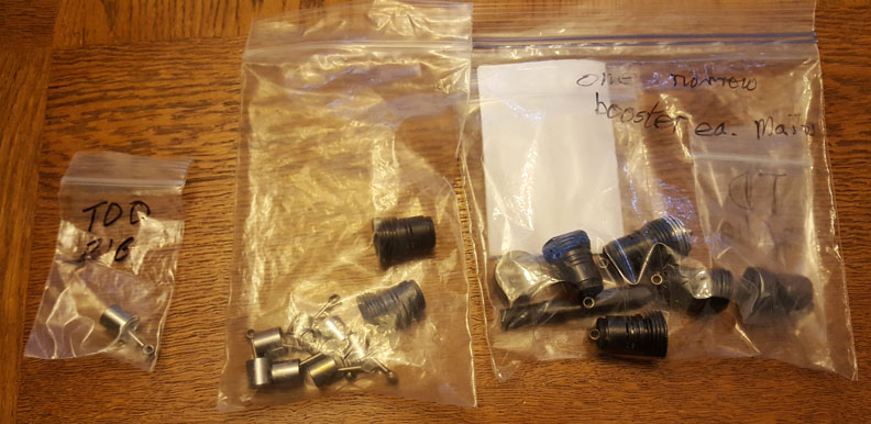
Cox engine parts. Orin Humphries photo.
In early February I bought a Tee Dee cylinder from Cox Intl. and a rod resetting tool. I had supposed that I really ought to get the rod tool to be thorough. Little did I know how badly I was to need it. In my fit trials above, I made a surprising discovery. Only one piston in 11 had a proper fit of the con rod, per Cox’s recommendation that came with the tool kit. They say the rod should have 0.002-0.003 inch clearance in the socket. I figure that is about the thickness of the oil film. The typical rod fit in this set of 13 pistons was around 0.020 inch! The worst one was about 0.040 inch. Call me disgruntled, but why isn’t Cox Intl. inspecting what they are buying before taking money from us and representing these items as good, RFI components? Now I have to take more time away from my aging F-84 project. I would like to have flown that someday before we all die.
Before arising one morning it crossed my mind that I should first have a break-in session for any piston/cylinder comparisons to be used later in the formal tests. The actual engine comparison tests should be done in as short a time span on that later day due to ambient temperature variation through the time of the test session. Nothing can ever be perfect, but we have to try to put limits on variations.
The pursuit of knowledge
The pursuit will never end. I don’t have everything figured out. We see some things and we make our best guess about it. Coming to mind is one of numerous sayings I picked up in Reader’s Digest a long time ago:
“Experience is what you get when you expected something else.” – Unknown.
Tales from the museum: Ben stories
Ben is one of the very top warbird mechanics in the aviation world. There isn’t an engine and airplane he can’t work on to my knowledge, other than current military, perhaps. He was a crew chief at the Reno Air Races for some years. One repeated job in Reno was being crew chief on Bob Hoover’s “Yellow Mustang.”
A big problem with race airplanes that have to look great is the exhaust stains. It took a LOT of elbow grease and time to clean them. The results were not perfect. One evening on the Yellow Mustang, Ben tried a different cleaner not common in those circles that he’d happened upon at a local store while foraging for supplies. It was Scrubbing Bubbles that you have read about in one of my earlier columns. It took 30 minutes to get through the baked on stains, the bubbles turning brown in the process. The job came out perfect for the first time. Another crew chief happened by and saw the only squeaky clean racer on the line.
“What did you use to get the exhaust off?” he asked Ben incredulously.
“Scrubbing Bubbles” Ben replied, showing him the can. The next morning, every crew chief at the Reno races had a can and all the airplanes were clean.
Ben brought his motor home to the races for the duration. He made it a habit to make coffee and pancakes in the morning for anyone in the pits who came by. It became the morning gathering place, focused on 8:30. Bob Hoover was a regular at these gatherings. One morning Ben was getting the coffee and griddle ready and he heard a voice behind him from someone at the foot of the stairs.
“Is Bob here yet”? He was looking for Hoover.
Ben turned, “Not yet. He’ll be here by 8:30. Would you like to come up for some coffee and wait”? Then, Ben thought the old gentleman looked familiar. “Are you General Doolittle?”
“Call me, ‘Jimmy’.”
“Yes, General,” stammered an astonished Ben!
“I SAID ‘JIMMY!’ ”
“Come on up, General.”
“I SAID ‘JIMMY!’ ”
“Uh, okay, -- Jimmy -- ”
General Doolittle found a seat inside and got a cup of coffee.
“I’m serving pancakes in a while. Would you like some,” asked Ben?
“Thank you”, said the General -- Uh -- Jimmy.
For several mornings thereafter, Ben served coffee and pancakes to Gen. Jimmy Doolittle.
I have another Ben story we can talk about if I see you at the Regionals. Ben is also a dyed-in-the-wool Control Liner from WAY back. He and I will be flying together this spring.
Flying Lines home page
Back to Scale Matters column main page
Back to Scale main page
This page was upated May 23, 2018

