Geezer Clown

By Ken Burdick
Geezer Clown race is a sad state of affairs, but then so are many things when you're a Geezer.
Time was, when many geezers actually flew high-speed Racing events such as Goodyear, Team Race and the big daddy of them all, Fast Rat. Somewhere before the progression of things Rat race was fun to fly, speeds were 120 to 140 mph. But along with improvements in engines and porting, the speeds inched their way up to 160 mph. 50-60% nitro fuel was not uncommon, special custom molded props began to show up and John Ballard was way cool.
I am one such geezer. We knew then we were looking at the end of it when rat race hit 160 mph, it was just too fast and we pretty much stopped flying the event. Goodyear became about the same sort of thing with very high speeds and increasingly quicker rotation speeds. If you said anything however, you were less than a player, possibly an early geezer. Currently, F2C or Team Race, is unthinkable to fly unless you are well trained have an abundance of cash, and in great physical condition.
Send in the Clowns
Clown Race was an attempt to allow newbies and geezers such as myself to pretend that we can still race. The event was quickly changed by more and more powerful engines and due to the natural progression of racers, has now become an event comprised of special engines, and speeds of 100 mph. Sound familiar? It's just the nature of things. I fought like hell to keep unlimited nitro content in the AMA's Speed events. It's just in the nature of competitive people to do things like that.
 NO ... Send in the geezers
"My story begins in nineteen-dickety-two. We had to say dickety because the Kaiser had stolen our word "twenty.“
If you can't do what you used to, it's still fun to do something like it.
Geezer Clown, or Sportsman Clown race as it is properly labeled, is such an event. The idea is to use low tech engines that are inexpensive, coupled with the Northwest Clown race rules to make a racing event that is a compromise to many ideas intended to slow the event event down.
The first Sportsman Clown Race is planned for Sept. 21, 2013 in Salem, Ore. See Where the Action Is for details.
Plain-bearing engines are not typically designed as racing, so the selected engines are O.S. LA .15, O.S. FP .15 and the Brodak .15. These are the engines suggested for this trial event here in the Northwest. The LA .15 is popular in Indonesia for F2D combat as a low cost reasonable power plant. They take some work but can be made to run a bit faster than stock. The OS FP .15 is tried and true. A three port engine that known to about everyone.
Which engine is better?
All of them run OK. The LA .15 requires some extra work in that you must use RTV on the plastic back plate to seal it to the crank case. The FP .15 is a workhorse and has been around for many years. Both are well made, but out of production. One of the most challenging parts of either engine is the use of nickel plating on the liner. There have been many reports by users of problems with the nickel plated liners. If they are used, oil content should be reviewed in your application. The LA has only two main transfer ports while the FP and Brodak have two main transfer ports and a boost port.
Restarts are possibly one of the more important criteria in this situation since none of them will be considerably faster than the others so know your metallurgy. The piston material and its fit in the liner will be most critical to an event like this one, and we want to spare the pitman's wrist. The Brodak .15 is the only one of the three currently being manufactured. The Rein Man won one of them at the 2013 Northwest Regionals and gave it to me as a thank-you for my pitting him in several combat events. The following is a brief review of the Brodak .15 from the perspective of racing Geezer Clown. If you have a nice LA or OS FP, then you're all set.
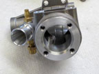
Brodak .15
Basic configuration:
Plain bearing: Crank case is grooved to allow oiling to the front of the crank shaft, from the fuel inlet port ,all the way to the front of the crank bore. There is another oiling groove on the opposite side of the crank bore that runs from the rear of the crank bore but stops about .250 from the end of the bore to prevent crankcase pressure from escaping. The dual groove is a very good idea.
- Porting: Schrunnle ports of reasonable size including a boost port.
- Piston: Aluminum, cut skirt for fuel flow to the liner ports. 20.5-22% silicon alloy.
- Liner: Aluminum / hard chrome plating / 11-13% silicon alloy.
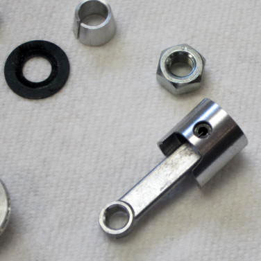
- Con-rod: Aluminum, no bushing
- Cylinder head: four bolt pattern, typical single bubble hemispherical chamber .003 aluminum head shim Total clearance to piston is about .020.
- Backplate: Aluminum, 3 bolt pattern with tight fit in the case. Clearance to back of the crankshaft .020. Paper gasket seals to the case.
- Crankshaft: 10 mm od, 7mm fuel passage.
- Venturi:. 026 id, Aluminum, removable with needle valve assembly centered in it.


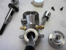
Impressions: All work appears to be done on modern CNC machinery and as such tolerances should be expected to be spot on. The RPM range has been stated conservatively with a maximum of 12,000 rpm. This is primarily due to the sport application, conservative timing and head clearance, with a very restricted venture. The smallish crankshaft hole of 7mm also contributes to the low RPM figures. It is important to remember the engine was not intended for racing and higher speeds. Higher RPM figures can be obtained by experimenting with head clearance and increasing the available venture area by changing to a smaller needle valve assembly. This will result in higher RPM, but also increased engine heat and increased bearing wear on both the con-rod and the crankshaft bearing. The best news is the hard chromed liner. It should be able to restart much better than a comparable nickel plated liner.
I was able to get some limited technical information from Brodak regarding the engine. It is a clone of the Brodak .25 that has been used for B Team Race in Australia and other parts of the world.
The engine is made in an Eastern country, possibly Moldavia, and likely designed by “Seregey” (no last name given) who has designed many F2C engines. The use of hard chrome and a well thought out aluminum piston and liner will produce an engine that can be used in mild forms of racing.
To market a model engine requires that you make a profit, otherwise there really is no point. To keep pricing down, it appears that the all-important finish work has been somewhat offset by use of good tooling. Hand finish work is a skilled process that can eat away any profit a manufacturer might think there is.
I did my own finish work on this engine using 2000 grit polishing paper, held by a tool. The liner ports looked good to begin with, but I carefully rounded each sharp edge, there were no burrs or chrome chips. The crank needed no work! How cool is that? The fuel exit hole has a chamfer and even the edge at the counterweight was slightly broken, so no burr was present. The fuel port was cut having no 90 degree angles so until mine breaks, I'll call it good.
If you do not know how to carefully do finish work, you could do more harm than good so be careful here.
My impression of the engine is positive and even if I had not done the finish work, it would have been fine to run as is. The piston fit is less tight than I am used to, but again, this was designed to be a sport engine and not a speedster.
Ground down!
Speed means nothing if you cannot get to the model in a quick and efficient manner, so we are going to talk about ground handling and lead-out position.
When the engine stops is when actual racing begins. There are no fuel shutoffs allowed so the geezer flying it will have to lead or whip the model around the circle now and then, if you have a feather weight model it will be hard to do. If you have one balanced for stunt, it will be impossible. Placement of the axles on the landing gear is critical to all of this. Try to get the axles 10 degrees in front of the CG. The CG for this application needs to be a click back from the leading edge, yes -- nose heavy, you old geezer.
When this has been done correctly, the pilot can get the model on the ground, give it a slight bit of down control allowing the model to balance on its axles. It will now roll quickly to the pit man as it is not dragging the tail skid and trying to grind it into the pavement. The tailskid should be such to have the model sit level or a very slight nose up.
Lead-out position also works with this ground handling system. The further back the lead-outs are, the more the model will point out. This is great for line tension and being able to whip the model but can slow the top speed some. The Clown model was designed for stunting and general flying, not barreling into a pit man. Experimenting with moving the lead-outs forward in small increments until your model is trimmed out for flying AND ground handling will produce results.
But wait, there's more!
The following are comments from Todd Ryan, who is perhaps the fastest Clown on the block. What follows will produce a solid model with the ground handling characteristics you need:
- CG at 1/8-1/4" behind back of leading edge.
- Front leadout 1/8-1/4" behind CG.
- Rear leadout 1/2-3/4" behind front leadout.
- 1/2-3/4oz tipweight.
- Landing gear mounted perpendicular to axis of fuselage (straight down from leading edge)
- 1.25" wheels.
- Soldered washers on landing gear with staybrite.
- Uniflow tank mounted with foam underneath it.
- Surgical tubing for pinchoff.
- Dubro fuel tubing.
- Fuel Filter!
- Landing gear nylon clips drilled all the way through fuselage and mounted with 4-40 bolts/Nylock nuts.
- 0-0-0 engine, wing, and horizontal stab alignment.
- Sealed hingeline on stab/elevator.
- Large control horn with pushrod in farthest out hole.
- 2 or 2.5" bellcrank w/pushrod mounted on nearest hole to pivot.
- 2" handle spacing.
- Monokote or equivalent high-temp shrink covering (overlap edges when covering by min. 1/4").
- Catalyzed paint (superpoxy, 2-stage urethane, etc.)
Good luck with your clown model, I'll send in pictures of mine as it's built.
--Kenny-b
See article on finished Geezer Clown
This page was upated Aug. 22, 2013
Flying Lines home page
Back to Racing page