![]()
Musings from the Combat Pits
Stooge designed by Mike Rule redesigned
and updated with electronic release
February 2021
By Buzz Wilson
Background
Over the years I have used many different stooges, both human and mechanical. All had some drawback or shortcoming.
In my opinion, the ideal Combat stooge should accommodate any Combat plane that you put into it; from 1/2-A to Fast, boom tail to fantail. The stooge should be easy to transport and set up. It should be safe to use – no false releases. It should allow easy access to the plane.
Of all the stooges that I have used, the one Mike Rule designed met most of these requirements. The following is my version of Mike’s stooge.

The one shortfall is transport and setup. Mike is a big guy with a big truck. His stooge is permanently set up – no problem transporting for him. Mine was a bolt-together. It worked but was cumbersome to transport and took time to set up.
Recently the Ukrainians have been producing stooges. The stooges from Ukraine satisfy the ease of transport and setup if you like working on the ground. A couple of years ago I bought a table and adapted it to hold the Ukraine stooges (below). See FL October 2018 Musings from the Combat Pits.

The problem with the Ukraine stooges is they will not work with a boomed airplane. Gene Pape recently designed a stooge that accommodates big block boomed planes as well as Half A. See Gene’s article Fly by Yourself, June 2020 Flying Lines for his electronic-release stooge.
The Ukraine stooges use a spring to hold the launch arms tight against the plane. When released the arms rotate down and the plane flies off the stooge. The Rule design uses a spring to provide a force to raise (rotate) the arms upward and the plane flies off the stooge. I will continue to use the Rule design.
Historically, stooges have relied on a string to pull the release, with the exception of the sleeve stooge (below). With the sleeve stooge, the control lines are pulled and the plane slides out of the sleeve. In 2008 — hard to believe it has been 12 years — I did an article on stooges. See FL 2008 archive, Stooges the Mechanical Type Original release June 2008, Updated September 2008.
Recently people have been converting electronic car door actuators to stooge release mechanisms.

I have decided after 12 years to update my version of the Mike Rule design to incorporate electronic release and to improve the ease of transport and setup.
Comparison 2008 stooge with 2020 stooge
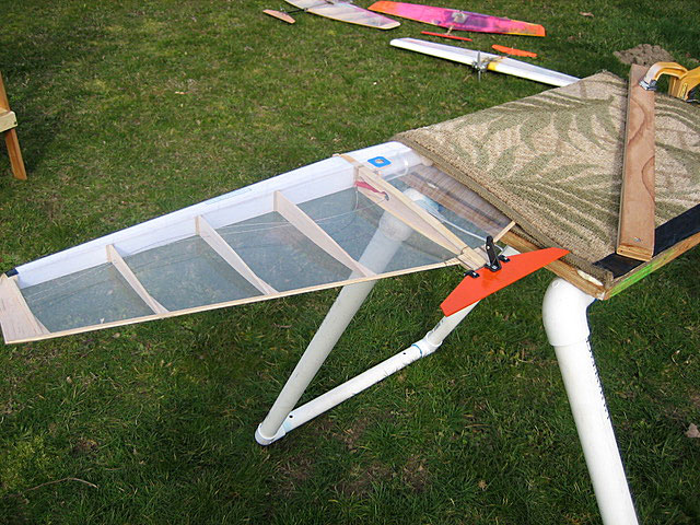
When you compare the 2008 construction photos to the 2020 photos you will notice that the main launch board looks similar.

The restraining arms are also similar.

To make it easier to transport (lighter and more compact), the torque box is replaced with a singular horizontal piece.

The horizontal piece is connected to the launch board using door hinges (Hillman 2½”).
Many of the Ukraine Combat planes use internal shutoffs. At launch there is some control resistance; you have no to little control until the plane gets line tension. When the plane leaves the stooge it wants to drop. To overcome this, the plane needs to be launched at an angle. This is one advantage the “hooman” stooge has. When you give the “hooman” voice commands it will adjust. Some are more responsive than others.
To create a launch angle, plywood (3/4 inch) is attached to the stooge sides. The angle of the legs is not that critical, but the height at the rear needs to provide good access to the restraining bracket as well as clearance for it to rotate.

By good access, I mean to be able to easily engage the locking system and to see that it is locked.
I added a piece of 1/8” music wire to lock the hold-down arms in place while the plane is being started. This is placed on the inboard arm.

Once I am ready to go to the handle, I go around the rear of the stooge and remove the safety lock.
Release spring
The 2008 stooge has a frame around it that is used to attach the legs. The frame also provides an attachment point for the release spring.
The new design does not use a frame; therefore an attachment point must be made for the spring. A piece of (3/4 inch) plywood is attached

The release spring is attached to the stooge in two locations using lag screws.
The release spring on the 2008 stooge is a tension spring. I headed off to the hardware store only to find they did not have any — off to Tacoma Screw. I had to purchase a longer spring than I needed. The spring that I purchased will need to be modified to work with the stooge. It will need to be shortened. Shortening the spring did not work; back to the hardware store to get something different.
Release mechanism and hold-down
The 2008 stooge used a Hold-Down Toggle Clamp Open Arm, STL 600_290# Cap, Neoprene Tip Spindle (McMaster-Carr Part Number 5126 A47). This combines both locking and release. The one advantage of hold-down toggle system is that once you set the plane on the stooge and lower the arms you continue to hold the arms down and with the other hand engage the toggle clamp. The plane is secure in the system. Pulling the release string will open the clamp and release the plane from the stooge.
Ideally it would be nice to use the Hold-Down Toggle clamp. However, it will not work with the new design because the solenoid does not have enough power to pull the handle clamp.
I purchased an InstallGear central locking system. The system consists of a main unit and four solenoids. A 12V battery is required to power the system. The Main Unit is what the wiring harness is plugged into. When you initially open the box and remove the parts, the wiring harness resembles the worst line tangle you have ever been in. There are wires for the four solenoids as well as wires for the power supply and wires for the car trunk and taillights.

Next I called Gene Pape and asked him about the wires. He said he threw most of them away. When you look at Gene’s stooge you will notice he uses two of the solenoids, one for each restraint. Next I started following and grouping wires as to which ones needed connecting. I added the small pieces of blue and green masking tape to help sort out the wires.
The restraint and release will need to operate using the push-pull mechanism of the solenoid. The solenoid locking mechanisms have a lot of slop in them. The nylon tip of the solenoid rotates. It is a loose press fit onto a nylon shaft. To eliminate the wobble I used thick CA to glue the two pieces together. The next problem is what size and how to attach a piece of music wire to the tip. A 1/8” diameter music rod is bent 90 degrees on one end and CA’d to the solenoid. Microballoons are used to fill the gap.

My first thought for the hold-down bracket was to make a simple bracket using wood and attach it to horizontal arm holder. All that would need to be done is to drill a hole at the correct height and position the solenoid so that it would easily move in and out of the bracket.
I am reluctant to rely on glue to fasten them to the horizontal arm holder. This has led me to searching around the shop to see what I have in the way aluminum or steel angle.
I found some aluminum angle, 11/8” x 11/8” x 1/8”, and cut a piece. I clamped the solenoid with the wire in place and then held the aluminum angle against the end of the wire and marked the hole for the release wire. This was drilled and the attachment holes drilled in the aluminum angle. With everything attached, I moved the solenoid into the armed position and then applied a force like the spring lifting spring would exert. When I did this, there was significant flex in the solenoid shaft – not good. I added a second piece of aluminum angle but attached to the main board and this solved the lifting problem.

Power Supply
The system requires a 12V power supply. From the days that I used a 12V battery and a power panel in my pit box there were two 12V batteries on the shelf. When I hooked them up to charge they both showed they were no longer functional. When I went to the Tower Hobbies website they were not available. Amazon had just what I needed — a ML5-12 SLA is a 12V 5AH Sealed Lead Acid (SLA) rechargeable maintenance free battery. The terminal sizes on the battery are F1. I replaced the connectors on the wires from the Main Unit with female F1, 3/16” wide. The ones that I found were made by Noble, item No.512M. I also made a charging harness to connect the battery charger to the battery. Again using the F1 connectors. The battery came fully charged. The final step was to cut the surplus wires from the harness and wrap with electrical tape.
Everything was wired up and the solenoid cycled. This revealed that the solenoid needed to be repositioned to get more wire extending through the aluminum angle. A retest and everything is working. One final test that I ran is a range test to make sure the unit is going to work at 60 feet.
The battery and receiving unit for the solenoid are placed into a case. I chose a Polycase DC-58P from Allied Electronics

This is setup such that the box can be removed for transport. When it is time to setup, the box is placed on the stooge table and the solenoid actuator plugged in. The key fob that is used to control the release of the solenoid is attached to my control handle. The second key fob is kept with the stooge to arm the system.
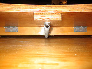
Attaching Stooge to Table
See FL October 2018 Musings from the Combat Pits for how the plywood table cover is attached to the table.
The stooge is attached to the plywood table cover using metal angle brackets. For transport, I want to be able to remove the stooge from the table cover. The first batch of brackets that I bought was too wide. I bought a second batch that is ½” wide and attached them to each corner of the stooge. Holes are drilled in the plywood table and the brackets bolted to the platform.

Initially the stooge was centered on the table. When I set a Half A plane on the stooge, the plane was too far back. There was a strong possibility that it would strike the table upon release. Remember, these have internal shutoffs. I repositioned the stooge to the front of the table giving the plane room to fly off from the stooge and gather line tension.
Finish
I have sprayed the stooge with a water-based spar varnish. I was not satisfied with the finish. I brushed spar varnish onto the wood. Once this was done I brushed on butyrate clear dope to fuelproof the stooge. The stooge less the battery and receiver weighs 8.5 pounds.
After setting a fast plane in the stooge, I decided to make one more change. A lot of my planes use external controls, which means there is hardware on the underside; specifically nuts and engine restraint wire. On the original stooge, you can see where, over time, hardware has dug into the plywood. With the variety of models that will be launched from the stooge I notched the center section to accommodate front-end hardware.


The final step is to cut the foam for the arms. I used Frost King insulation. The foam has a sticky back, but over time will come loose. Wire ties are used to hold it in place.

Not counting the collapsible table, I spent about $100 on materials. My original Rule design cost about the same in 2008 and has lasted for 12 years. It is in need of a refinishing, but still functional.
The final shots show a Fast, F2D, and 1/2-A in the stooge. The Fast and F2D planes are held in the stooge with the foam. Because of the thinner airfoil on the 1/2-A planes they want to slide toward the outboard. This has never been a real problem and can be solved with some foam shims. Typically there is enough weight from the lines and handle to keep the plane centered.


Flying Lines home page
Back to Musings from the Pits main page
Back to Combat main page
This page was upated Feb. 10, 2021