![]()
Scale Matters
Vacuum molding
Fillets, etc.
By Orin Humphries
December 2018
My F-84E project has had two occasions to need small details where vacuum molding was the best way to make them. Fortunately, Micromark offers a neat, complete unit, and you can save some money by ordering it online, at least as of this writing.

The machine from Micromark, and a typical mold. All photos by Orin Humphries.
My model needed some small ducts that appear in the full-size bird at the American Airpower Museum in East Farmingdale, NY. There, Richie Criscuolo has been indispensable for my project with his many measurements and photos of their F-84E.
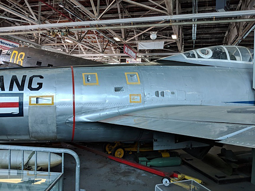
Right-side view of the F-84E in the American Airpower Museum.
Some time ago I made the canopy plug for my model and a rubber mold of it, again using molding supplies from Micromark. That is very expensive stuff. With the rubber mold I made a plaster cast and had some plaster left over. I poured the excess into two handy containers, figuring I would be using these for making small details later (now).
 Plaster
Let me get into the subject of plaster casting that I learned from my close friend and fellow teacher (retired), Scott Thompson, of Spokane, Wash. He taught art across the hall from my science class at Libby JHS in the 1970s and '80s. This is how you mix it up. You buy regular plaster and get some vessel for the mixing of it. Water goes into the container, leaving room for the plaster, which is a solid in powder form, and it takes up room, too. It is not like sugar that dissolves. You need a sifter to add the plaster to the tub a little at a time. The sifter prevents dry lumps from existing in the final mix. As you add some plaster, it will float on the surface for a bit, settling into the vat visibly around the edges of the plaster “raft.” When the latest raft has fallen into the water out of sight, you sift in some more plaster and wait. After some time, the rafts take longer to disappear, and you will be able to vaguely see the plaster under the surface of the water as it builds a central mound. The peak of the mound will finally stay just on the surface of the bowl. You add a bit more plaster until there is a bit of it that won’t fall into the water. That is the stop point.
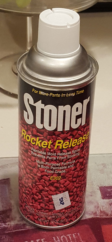
Now, you stir the water and plaster mound all together, and pour it into whatever mold you have prepared for making the cast. You have beforehand applied a mold release agent to the thing you are going to cast. For many such operations I like a product by Stoner called Rocket Release (right) that I got at the local TAP Plastics store in Lynnwood, Wash. They have branches around the Puget Sound.
The plug/mold that you are putting into the vat to make the cast will be very buoyant in the dense water/plaster mix. Make provision in your setup of the vat and subject to prevent the plug, as it is called, from floating up out of the vat.
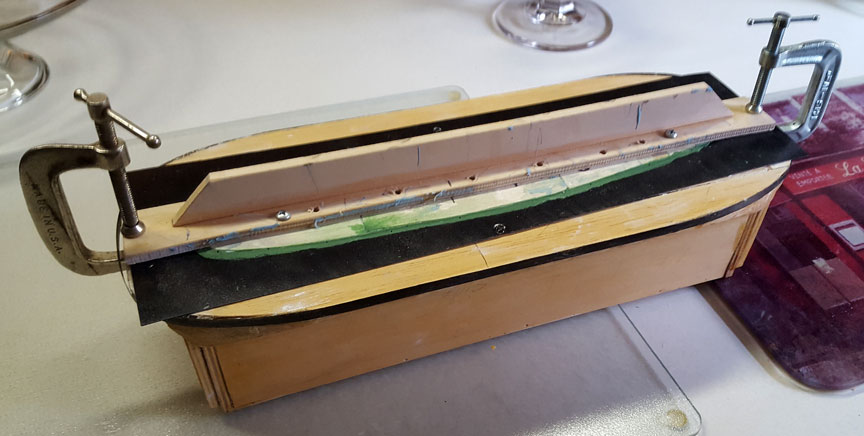
The mold clamped.
The plaster will be set in a few hours, but it will be wet with excess water throughout the body of it. I put my molds in the oven at a temperature below boiling (!) for a few hours to speed the drying. It may be a couple of days at room temperature afterward before the mold is totally dry.
Carving Details
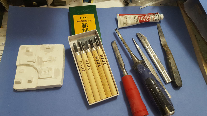
Handy tools for carving the piece.
I bought small chisels from Micromark, the set that you see and also the single, 1/8” wide chisel. The others, of course, are carpenter’s chisels in 1/2” and 1/4” widths. Also you see an X-Acto small handle with its chisel blade. The two small plaster samples are needed for getting used to what you can do while carving, that is, how deep a cut can you make in this medium without its chipping out some material that you wanted to stay there.

Plaster ready for carving.
I was encouraged by my results in trial carving of the samples, so I got good pictures of the small vents in the F-84 from Richie.
You can see the engraving I did into the plaster of the numerous duct shapes that I needed. The deep shapes require a small relief angle carved into their sides for later removal of the plastic parts. Also, with this particular machine, keep our carvings out of the square corners of the platen. The heater is not square; it has an oval shape, so the corners of the plastic stock don’t get the best heat. (Online, searching on “vacuum molding,” I saw a similar unit that had a square heater. That should make better use of the corners of the platen.)
Click on the photo to see the details more clearly.
For the plastic sheet I used ABS sheet stock 0.010” thick from the Plastruct line at the hobby shop. You can also use the lids from margarine tubs and Cool Whip tubs. Et Cetera. So, you clamp the plastic sheet stock into the frame and rotate the heater over it. The ABS plastic will at first start to wrinkle unevenly, and then it will even out without real sagging. Be patient. In a bit the ABS will start to give off visible gases. That is just residual solvents from its manufacture outgassing. Right after that the sag in the hot plastic become significant, and it is time to do it. You turn on the vacuum pump and lower the platen onto the mold. I leave the heater on for half a minute or so before turning off the heat and moving the heater away to the side. Keep the pump running for a minute or so longer while the hot plastic cools. Finally, you turn the pump off and wait for the plastic to cool further. After that you just unclamp the plastic sheet and inspect the result. You should be prepared to make several runs with fresh plastic as you get familiar with the behavior of the system and how the mold turns out. It is no dark magic; just a little practice and you will be happy with results. It is good to have spares, anyway, right?
For my small ducts, I decided to cut them out of the sheets leaving the surrounding panel areas still on as I see them in the photos. This made mounting the ducts simple. For that I used my small X-Acto handle with its chisel blade to inlet the skin around the duct openings in the fuselage skin. This gave me flush-mounted duct panels. It also created really scale skin seams there.
Canopy
I mentioned early on that I had molded the canopy plug in silicone rubber from Micromark. Below are some photos of that. For this project my canopy was just too long to properly fit into my large vacuum molding rig. It would sit in the rig kitty-corner, but I knew I could not get faithful molding of the canopy at either end with no adequate periphery between the plug and the box. I emailed my acquaintance, World Scale Guru Dave Platt, and asked him where I could get copies of the canopy molded for me. Dave referred me to Nick Ziroli Plans, which I found online.
Lauren Ziroli got back to my email to them and said I could send the canopy plug to them for evaluation. Upon inspecting the plug, Lauren offered to make me three copies (my number) for $20 apiece. I was surprised at the low price for such a small run. In due time I had my three canopies plus an early trial one by them to practice my next steps on.

The canopies and molds.
Butter Tub Lids
A good two years ago I had first used my small vacuum rig to make details for the nose wheel well equipment in my -84. You see, the brass and links from the machine guns on the top of the gun deck were collected into bins either side of the nose wheel. The waste was not passed overboard, unbalancing the plane. These bins in the full-size plane have three doors on their bottoms that the armorers empty after a mission. The doors have stiffening beads formed into them. I decided to add this scale detail to my model.

The brass bins.
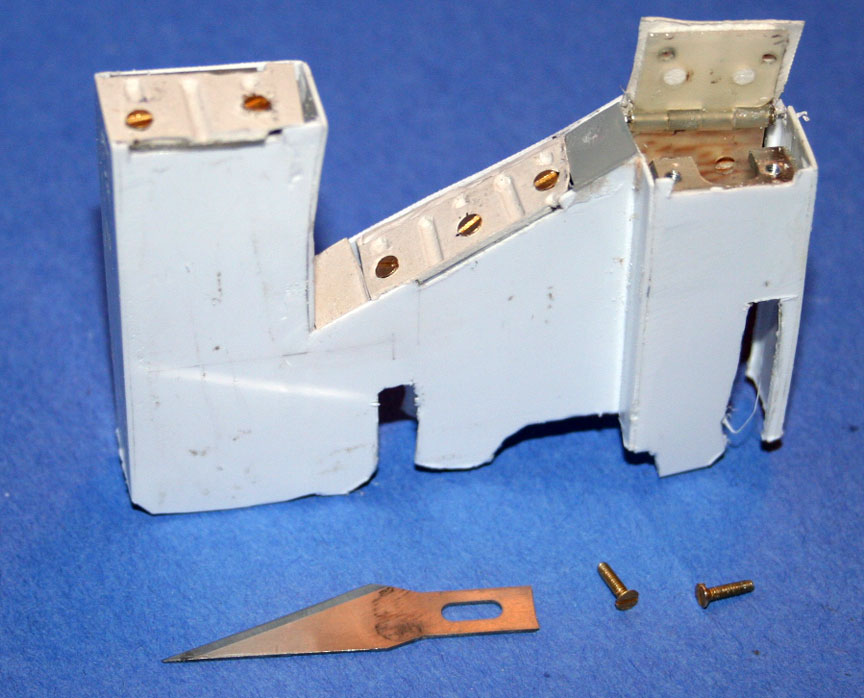
Close-up of one bin.
To get the stiffening beads into the door molds, I used short strips of half-round styrene stock by Plastruct from Galaxy Hobby in Lynnwood. In my Micromark vacuum molder I tried the plastic I had saved from a large margarine tub. It worked beautifully! So I asked my wife not to throw away the lids from Cool Whip tubs for future use.
The bins after weathering.
Well, there you have it, vacuum molding for scale details.
Reminder, another subject:
“Keep your leadout guides a hair below the as-built CG or lose it to a gust.”
Potpourri
Old Enya
I will be resurrecting an old model that suffered severe damage and was set aside in the 1970s. It is a VECO Mustang Stunter that has an Enya .29RC from the 1960s. One minute on the heat gun freed the engine, but the carb’s barrel was corroded solidly in the body. It is a dissimilar metals thing.
First, I found some MECOA-made new Enya carb bodies for the .29 for $7.50 and barrels for $4.50 on eBay, FYI. But what to do about a muffler for an engine that never had one? This is a Model #5224 engine, having no Roman numeral on the bypass (odd). The carb body has a square base. The exhaust stack edges have center-marks where a muffler theoretically could be mounted. I found that there is enough margin in the stack sides so through-bolts could be used to mount a modern muffler. (Back in the day, this engine sported a tongue muffler.) For some reason that I am not aware of, now, I pulled and OS #842 muffler out of the stash and checked the dimensions against the Enya’s. It was a perfect match.
A little session on the drill press produced the holes for the #4-40 through-bolts that came with this muffler. The OS muffler bolted right up to the Enya crankcase. Now, what are the odds that would work? Why did I even try this? “Things that make ya go, ‘Hmm?’.”


The OS muffler mounted on the Enya .29.
Fillets
All my adult modeling life I have been making wing-fuselage, etc., fillets by mixing microballoons and epoxy putty. It all started when the dope in those areas made paint fillets randomly on my A-26 in 1969. You sand the fillets when the epoxy is cured, and that opens up the microballoons on the surface of the fillets. Those are micro-pockets. The paint gets inside the pockets and fits like a lock in a key. It is not possible for the paint to later shrink and make ugly paint fillets.
Decades ago a club friend, Gil Horstman, and I heard another member complaining about paint fillets on his current project. We together explained the then-new microballoon method for fillets. We explained the need to sand them to open up little locking pockets. At the next monthly meeting our friend complained that he still got paint fillets. He then told us that once the fillets were cured and sanded he smoothed on a coat of straight epoxy, “ … so it would be smooth.” Gil and I were exasperated, and we once again explained the purpose for opening up the micro-pockets by sanding.
I always used the common structural epoxies for making the putty, and the longest-drying-time epoxy had to be chosen, 30-minute. It took five days for the epoxy to cure to the point of sandability. That was a pure pain, but the lack of paint fillets was worth it.
Now, on my undying F-84 project, (will fly Jan. 27 or I will turn purple), I tried Sig’s 90-minute epoxy first for the wing fillets. It, as expected, significantly extended the working time with the putty. You still have to wait five days for a cure, or, you can kick the epoxy gently with a heat gun. Don’t get it hot, just warm.
I next tried finishing resin instead of structural epoxy for the ventral fin. Holy Cow! Where has this been all my life? I mixed and applied the finishing resin/microballoon putty at 10:30 a.m. and it was sandable at 8:30 p.m.!!! No more five-day wait!
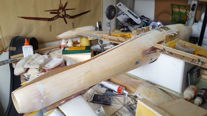
The ventral spine.

The ventral fillet.
There is another difference in the resulting putty mixes between using structural epoxy and finishing resin. The structural mix is internally stronger and it behaves a little better when you are smoothing the fillet. It stays together better. The mix with finishing resin can pull apart from friction as you smooth it. I did get satisfactory results with the finishing resin; you just have to be gentler as you work it. Don’t use water on your finger as you smooth the finishing resin mix; use alcohol, shaking off the excess before touching the fillet. Don’t over-work it.
I built the ventral fin with a 1/64 plywood spine as it will take a beating. That was quite a challenge due to the fin’s running 45% of the fuselage length and tapering early down to a needle.
I wet my left palm with water and my fingers as well so the putty won’t stick to my hand as I form it into a little roll for application. On the model I wet my finger or dowel with alcohol, shake off the excess, and smooth the fillet. I sand it later on with 220 grit.
The first version of microballoons was made from glass and the powder was white. Then, a product made from phenolic came out and it was a brown powder. When I began my F-84 I still had a remnant of the glass balloons. I used it up and now I am using the brown phenolic balloons. I find that the glass balloons are much harder to sand and you easily can damage the wood next to the fill. I had preferred the glass version as it made for stronger joints. Now, as I write this, I realize that an overly strong joint will only result in the wood next to it breaking anyway.
Addendum: Super Fil
EDITOR'S NOTE: The following update was added by the FL editor after discussion with Orin, who had been unaware of the product mentioned below.
A good fillet alternative being used by many CL fliers now is Super Fil. This is a two part (1 to 2) epoxy filler that is easy to work with and can be sanded. Best of all, dope and other paints will stick to it, as long as the modeler is careful to clean the fillets with alcohol or some similar cleaner -- and not touch it with oil fingers after cleanup.
Super Fil, which is designed for full-scale aircraft, can be purchased in large quantities from Aircraft Spruce, or in small quantities from Brodak. The Brodak is more expensive per ounce, but I the product has a shelf life, so buying the small quantities fresh from Brodak more often results in less waste.
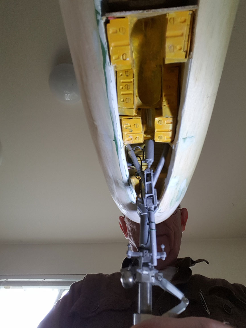
Pushrod hookup
Sometimes a model has a high-mounted horizontal tail, and connecting the pushrod to it directly, slanting upward, isn’t the best way. In the 1970s several of us independently invented a better way. Sorry for the crude nature of this sketch:
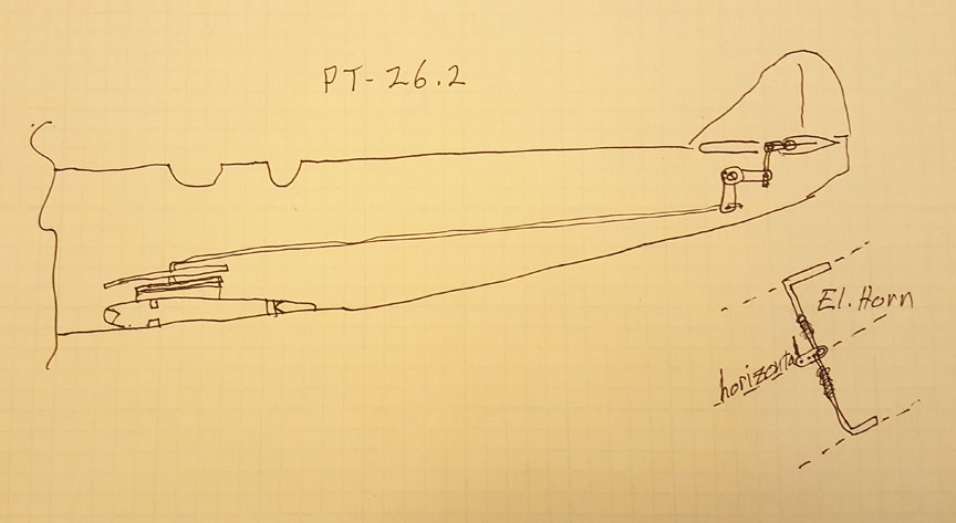
The intermediate bellcrank is shown at the bottom of the fuselage on the right.
You simply put an intermediate 90° bellcrank under the elevator hinge line. It takes in a horizontal throw from the pushrod and turns it 90° upward. The horn on the elevator has to be modified to run horizontally instead of the usual vertical orientation. Typical models needing this arrangement are the F-89 Scorpion, the OV-10 Bronco and the like.
Flying Lines home page
Back to Scale Matters column main page
Back to Scale main page
This page was upated Nov. 28, 2018