Scale Matters
The cockpit is a major part of any scale airplane. In this article, Orin gives tips on how to create a realistic instrument panel. All photos by Orin Humphries.
Instrument dials and placards
and other details
By Orin Humphries
October 2021
How to make dials for cockpit detail at your scale when none are available has been an age old problem. Making placards has been a non-starter. I first started doing this in the early 1970s with larger format film cameras and using an optics formula for sizing. Today none of that is necessary. Copy machines at places like Office Depot do the dirty work. If you try to make dials at a small size the lines are fuzzy and wiggly.
Dials
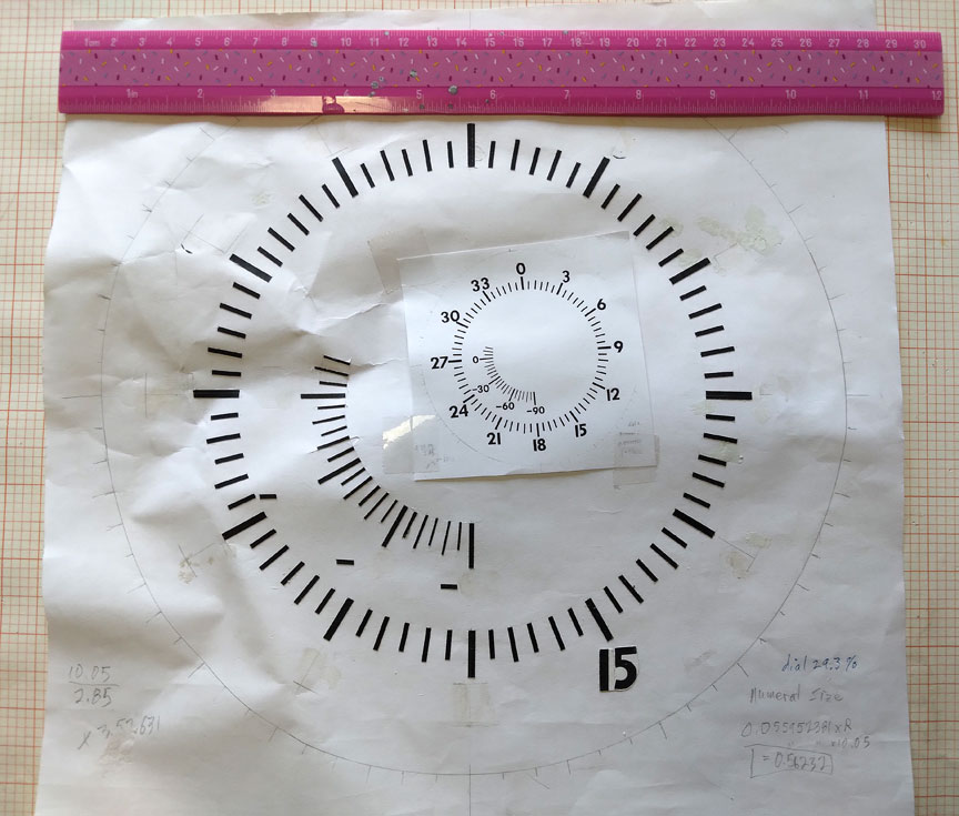
You see in the picture above the original large pattern and a reduction of it superimposed, an intermediate step.
You can start by making a large dial on white paper with a black felt marker. You see that this is a negative of what the final product will be. I usually start with a pattern size that is at least four times larger than the full size dial, the bigger the better. So for a 3-inch real instrument dial, the pattern would be not smaller than 12” across. The pattern size you choose must be a convenient multiple of your scale factor. That is, for a 1/12, 1/8, ¼, etc., scale model, your pattern size multiple would be a factor of two. For 1/3 or 1/5 scales, your multiple would be factors of three or five and so forth. This is for the reduction process to follow. Commercial copiers don’t go below 25% reduction, FYI.
The huge advantage of working at such a large pattern size is that the small bobbles you make with the felt marker virtually vanish in the reduction process. It is also much easier to get the angles for the individual markings located well when you are making a large pattern.
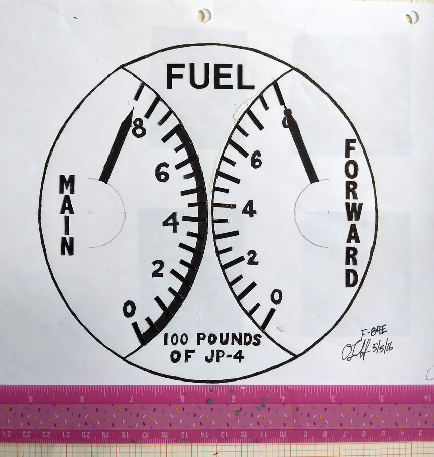
Though I began this years ago with a felt marker, today I use Chart Pak tape for the lines.
The color markings on many dials will come later in the process and are no problem.
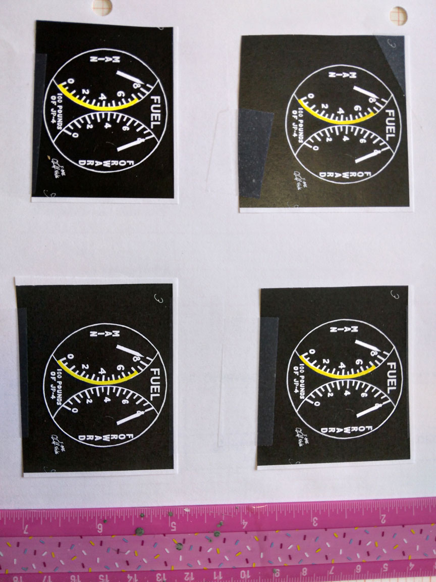
The dials in color negative.
I bought factory drawings from the Smithsonian’s National Air and Space Museum. This is expensive and takes a good six weeks waiting in the queue.
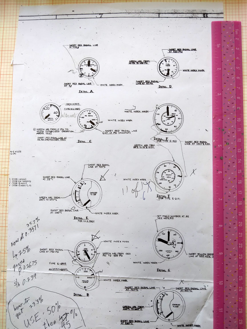
First reduction of the dials.
After some reduction steps I switch to transparency material instead of paper. I also specify NEGATIVE for the next copy. At this point I color in the limit markings.
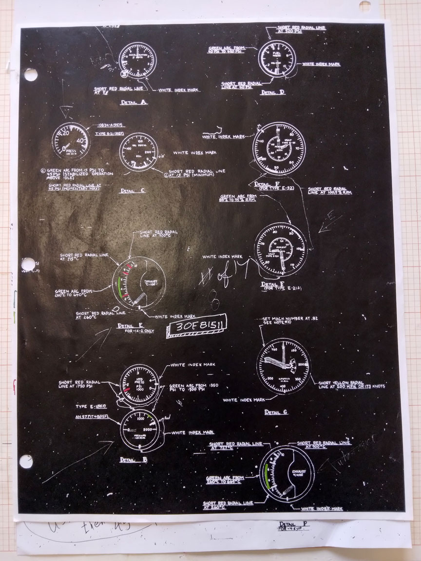
Dials negative colored reducing.
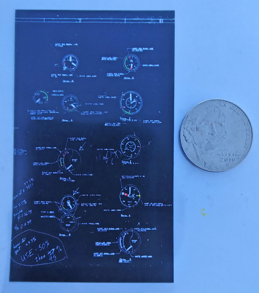
Dials transparency.
I used this procedure to make a full-sized dial for the Museum of Flight’s YO-3A When I restored its instrument panel.
Placards
(I cannot find my original pattern for this next, but a reduction of it follows.)
I made my pattern large, of course, and used in this case Monokote Trim as the background. The choice of size is driven by the size of available stick-on letters from a craft store like Michael’s. This pattern will have to be reduced on the copier and your goal is to get the letters in the final scale placard down your scale size for ½” ones in the 1:1 aircraft, if that is the size on the 1:1 subject’s panel. Be that the case, then your sizing of your pattern will be multiples of ½”, i.e., four times, eight times and so on.
Reduction
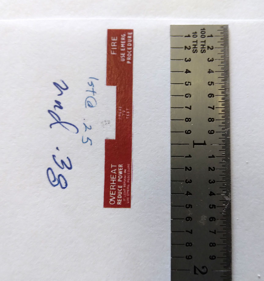
Reduction of a placard.
I have misplaced the large original pattern for this fire warning placard. See the following for more details.
For the lettering I used a white ballpoint from Michael’s.
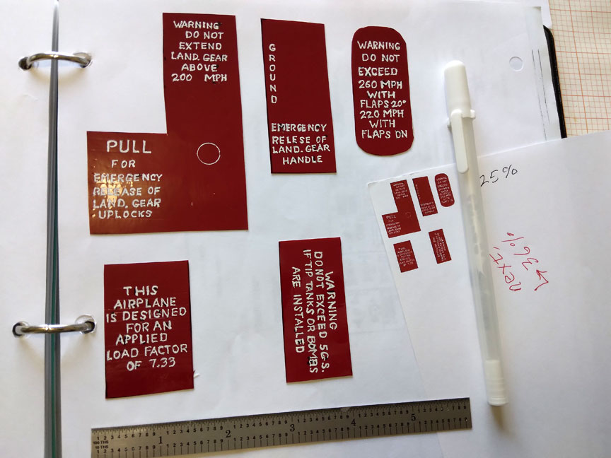
Reducing the instrument dials and the placards that have black backgrounds and white letters is the same.
Some placards I typed on my computer and then took them through the process above.
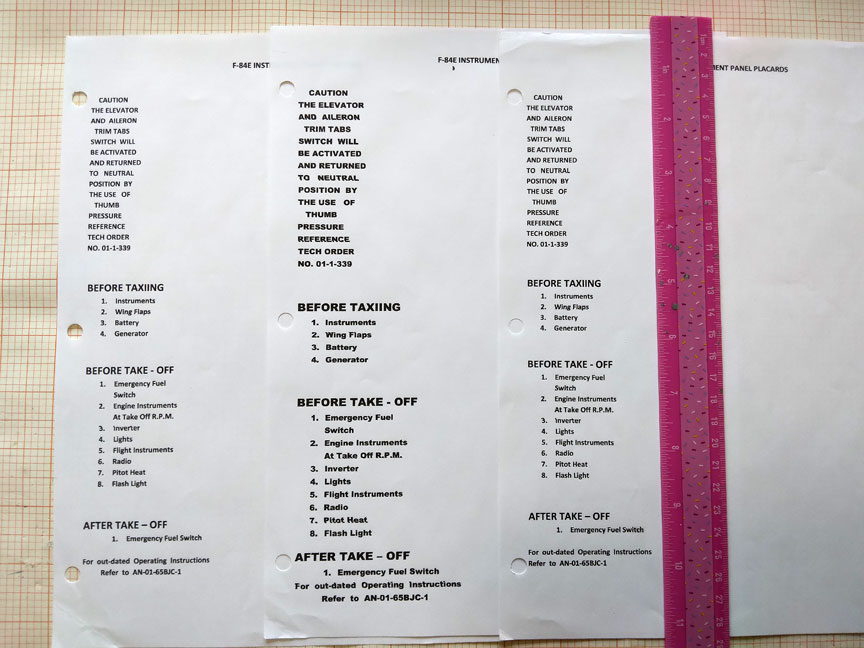
The typed lettering for placards.
These of course will have black backgrounds and white letters.
Radio panels and others can come from the factory drawings.
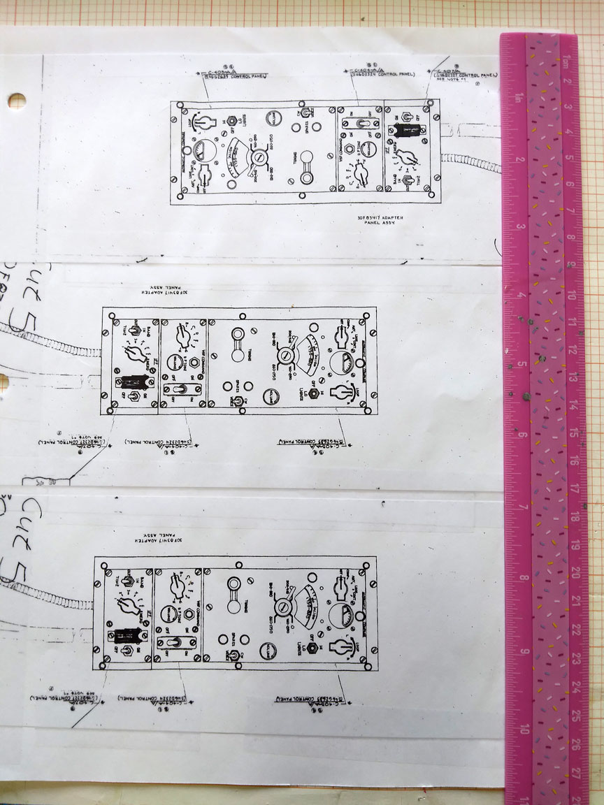
Panel radio drawings.
Reduce them and move to negative transparencies as above.
Black backgrounds with colored markings
What we are aiming at are dials with black backgrounds and clear slots for the hash marks and color marks. The dials will be mounted upon a white paper background in the instrument panel. The white paper will show through the clear slots in the little dial. The light rays off the white paper will pick up the color markings on the way out. So, onward we go.
Reduce the large pattern in several steps on white paper. STOP when you are two reduction steps away from scale size.
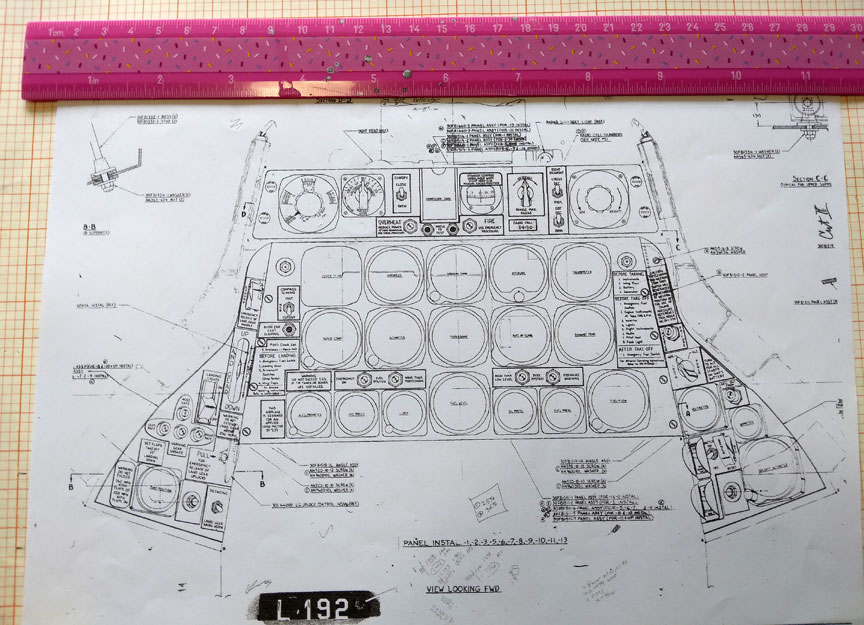
Panel reduced from factory drawing.
Black out the areas that you want things to show through the ultimate transparency as below.
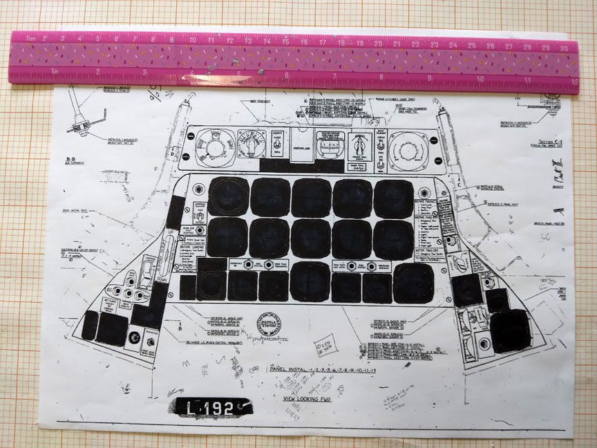
Change from paper copies to a transparency.
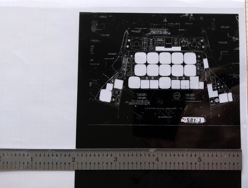
Negative transparency.
Dave Platt is an acquaintance and he has a great set of CDs out on scale detailing for sale. I highly recommend them. In his section on cockpits he said that he can’t make great placards so he just scribbles them. “You can’t read them anyway.” All due respect (!), my placards can be read if you have good glasses.
Bezels
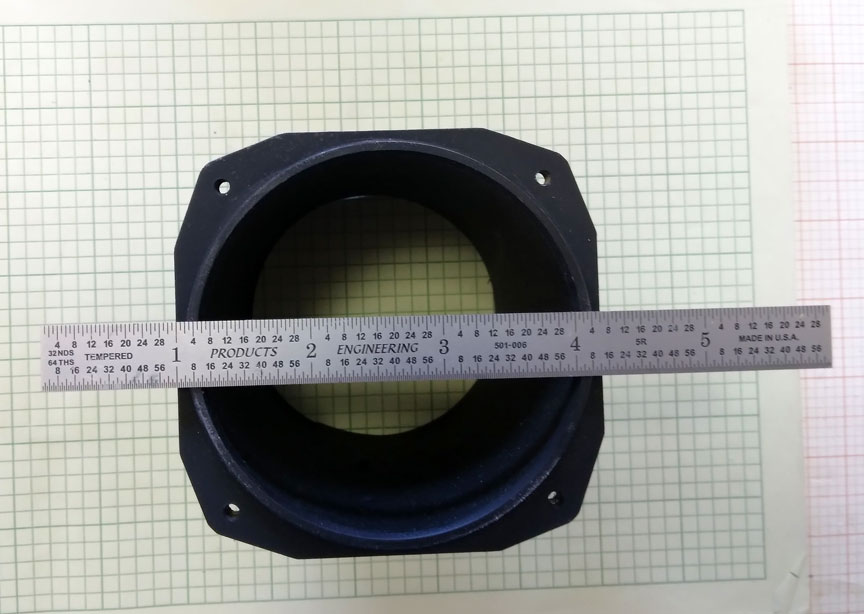
Here is a full size bezel and instrument case I made for the Museum of Flight’s Restoration center when working on the Lockheed YO-3A Project.
If you have to make your own bezels as I did on my F-84, “Hoo-boy!” You need to be planning to go for the gold at the Nationals to want to do what follows! You could opt to make simpler ones for lack of time to make the real deal.
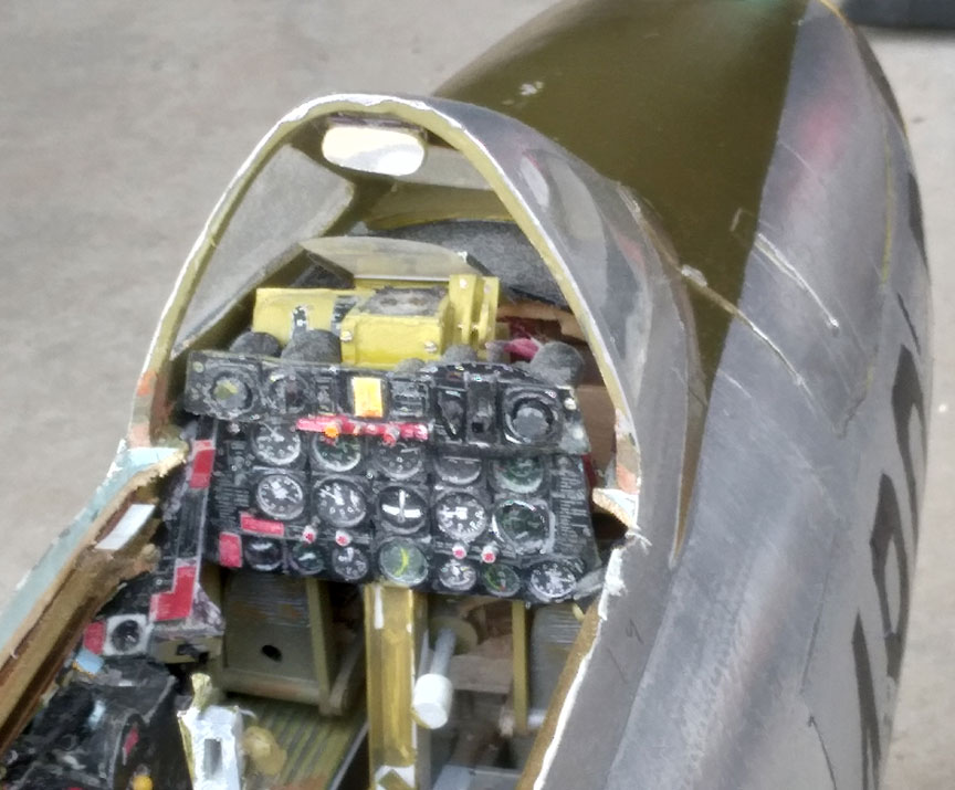
Bezels can be seen in the cockpit.
For the bezels I first cut strips of sheet styrene from the Hobby Shop. Holes in them were made with a tool from Micro Mark or Amazon. These were then snipped into squares. There are multiple bevel angles in the periphery of a bezel. I put on a head magnifier and used a sharp No. 11 blade.
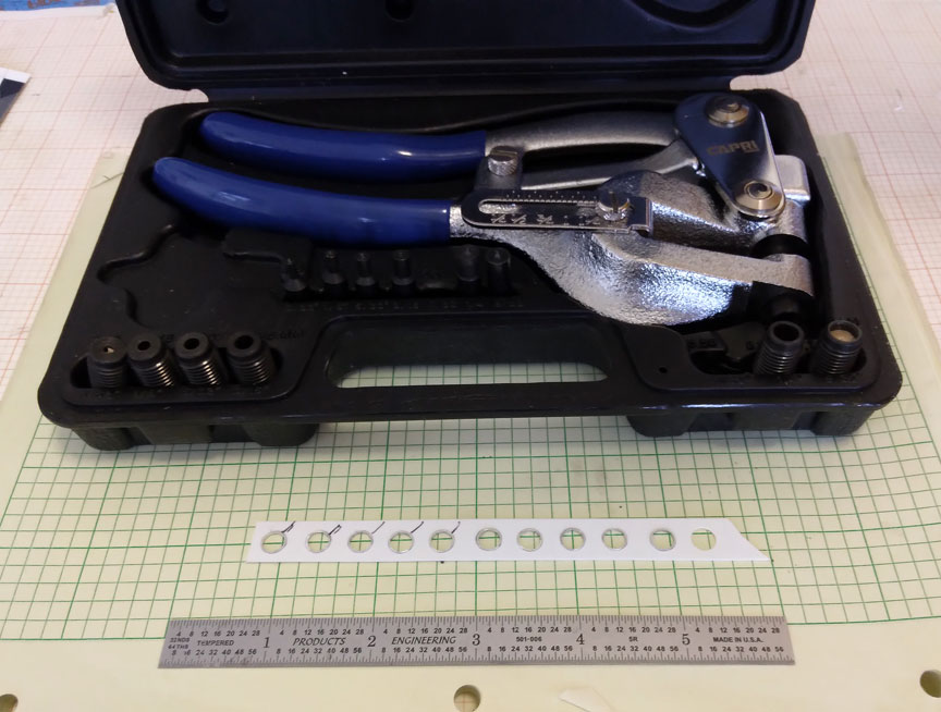
Capri 21050 Tool for the holes, and first step.
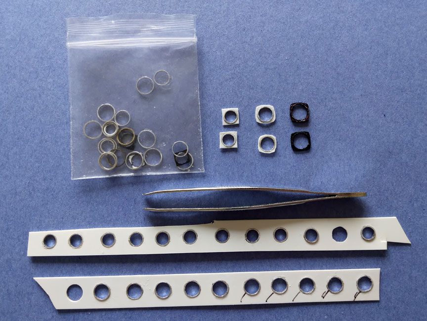
Bezel strip parts.
I made the rims inside the bezels around the hole by cutting thin slices of aluminum tubing with the small cutoff saw I got from Micro Mark.
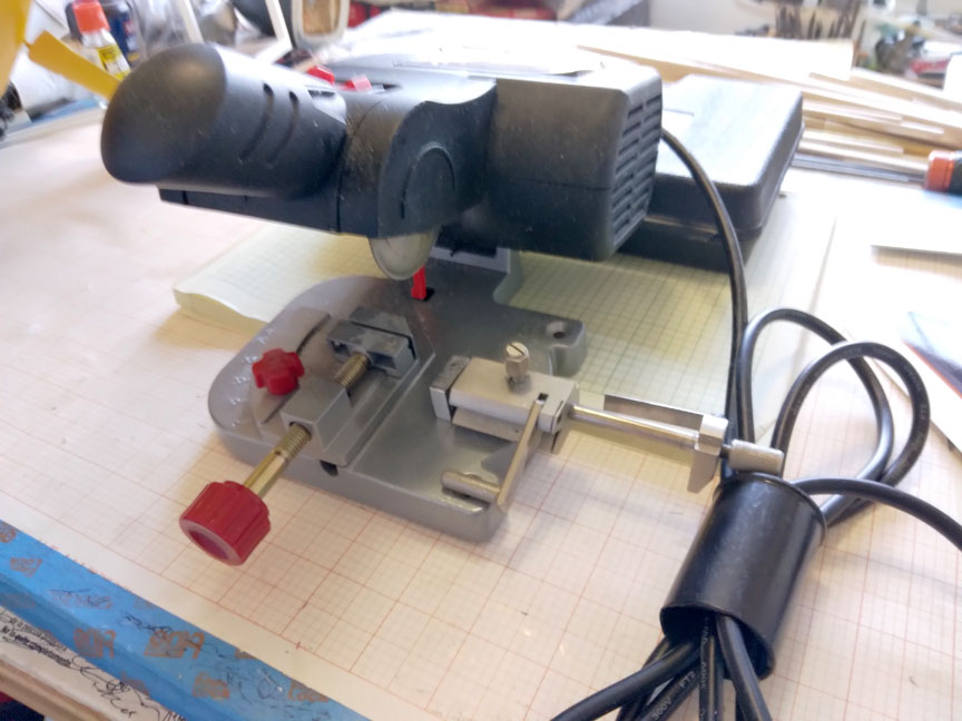
Cutoff saw from Micro Mark.
Gunsight
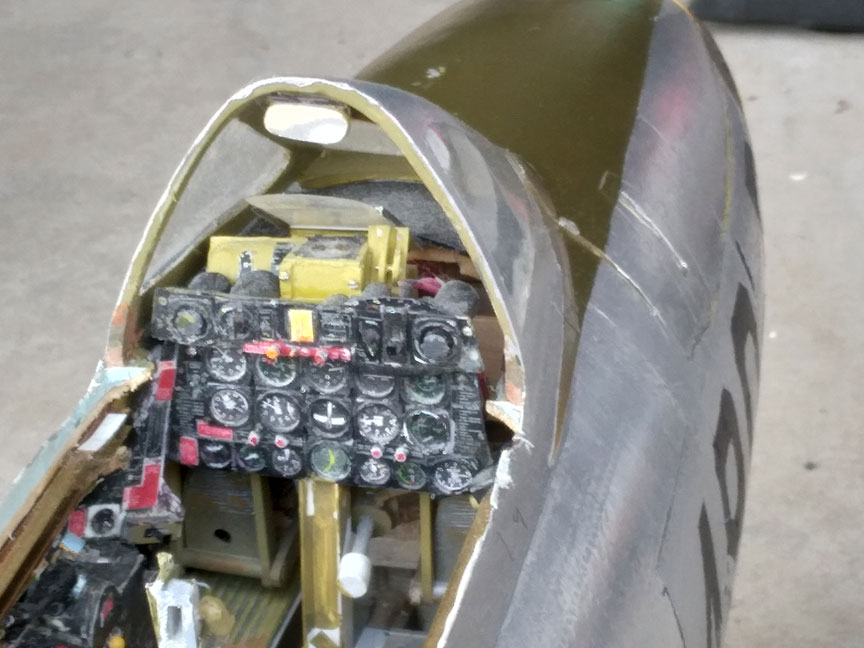
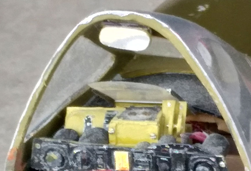
The gun sight.
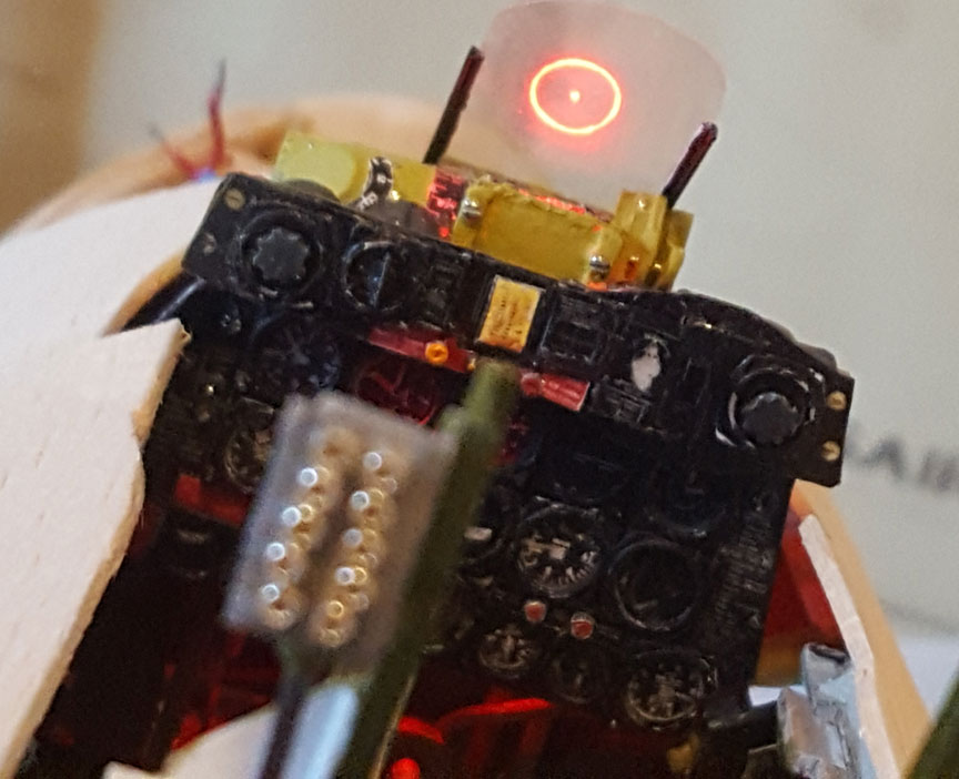
The reticle.
I got the idea from Bill Harney who was the first to present a projected reticle in his Zero at the 1973 Nats in Oshkosh. I was a Scale judge there. His illuminated when you squeezed a hidden micro switch under the skin in the leading edge of his right wing out near the tip. He put a photo negative of the reticle over a vertical tube which projected the light from below up onto the slanted sighting glass. Today you could use the dials process outlined above to make a transparency of the reticle.
My gunsight is my own invention. Let me say first you have to buy a “daylight bright” LED from Mouser Electronics. What looks sufficiently bright in your workshop will be invisible to the judges in daylight. I mounted the LED at the bottom of a styrene tube and made an occulting disk to sit at the top. The diameter of the disk was 1/32” smaller than the ID of the tube. The disk was thick enough to form a straight walled thin channel for the light rays to go up through. The thickness prevented stray light rays from going crooked through the orifice and fuzzing the image on the glass. I call this a “coherent path system.”
Making the dot in the center of the reticle was a delicate job. I have a set of number drills from 61 to 80 from Micro Mark. A pin vice held the tiny bit and I had to use great care and have patience to make the central hole in the disk. Not much light was going to make it through the tiny hole so I made a light gathering feature in the bottom end of the hole. I twirled a normal size drill bit with my fingers there. The larger cone shaped pocket intercepted more light and funneled it into the hole.
I mounted the disk to a thin disk of clear plastic that was larger than the OD of the tube. I fastened the plastic sheet to the disk with super tiny screws I got in a set from Micro Mark. This assembly was then glued to the top of the tube. My gunsight light switch is mounted in my instrument panel in the scale location. The tiny switches used throughout my cockpit lighting system were obtained from the control decks for old CD players that Ben Olson gave me. Lots of good little switches there for appearances.
Rear View Mirror
The mirror made from the case of a chrome tape measure.
For my mirror I settled on cutting up a small Stanley tape measure that had a plastic case that is plated with chrome. The central disk on one side is flat and after removing the label I cut the mirror out of it. Viewed from behind this mirror really stands out!
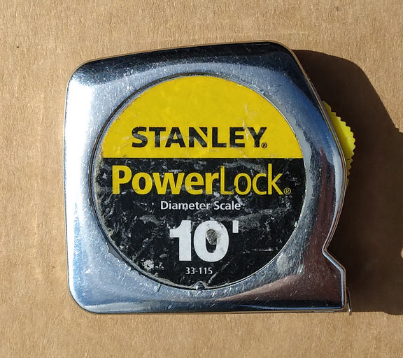
Chrome mirror was cut from this tape measure case.
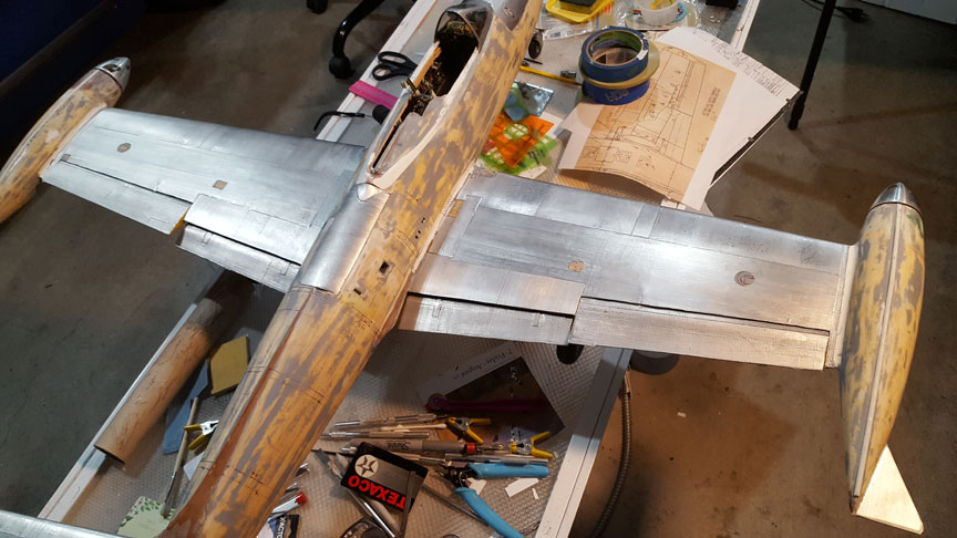
Later this year I will do an article on covering with aluminum foil as I did on my F-84, seen below.
Flying Lines home page
Back to Scale Matters column main page
Back to Scale main page
This page was upated Nov. 9, 2021

