Scale Matters
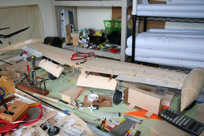
The F-84E Thunderjet wing on the workbench, with flaps down. All photos by Orin Humphries.
I-beams revisited
By Orin Humphries
January 2014
My F-84 wing is complete and now the fuselage frames are getting detail design work. This project is really complicated due to my desire to have a lot of scale features. There are huge cutouts in the fuselage that of course has to withstand pull tests. Not the least of which are the cockpit, receiver access panel, dive brake, nose wheel well, nose gun bay cover, internal air ducts and on.
Years ago I wrote a piece in this column on the best beam I ever saw for a model subject. It followed engineering practice by making the load bearing being done by the chords of an I-beam, not the web between them. The chords are the upper and lower caps of a capital “I”. The chords are made of a stronger material, such as 1/64th plywood or sometimes spruce. For the web in this super beam design, you use light weight material like balsa or even a plastic foam in some cases. The loads in the web are always small at any point within. This is why it is hugely mistaken to use plywood for webs. That makes the model fly like a 2x4. (Yet modelers seem staunchly resistant, picture the Rock of Gibraltar, to substituting lighter materials in the web.) (That is a primary trait to the human species: not listening to someone who knows and going with your own gut feeling. Am I exaggerating here?) But I digress.

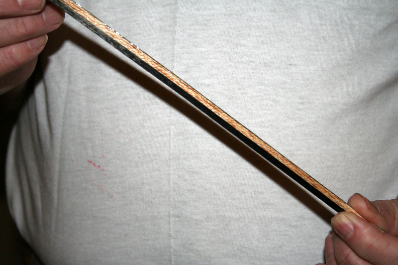
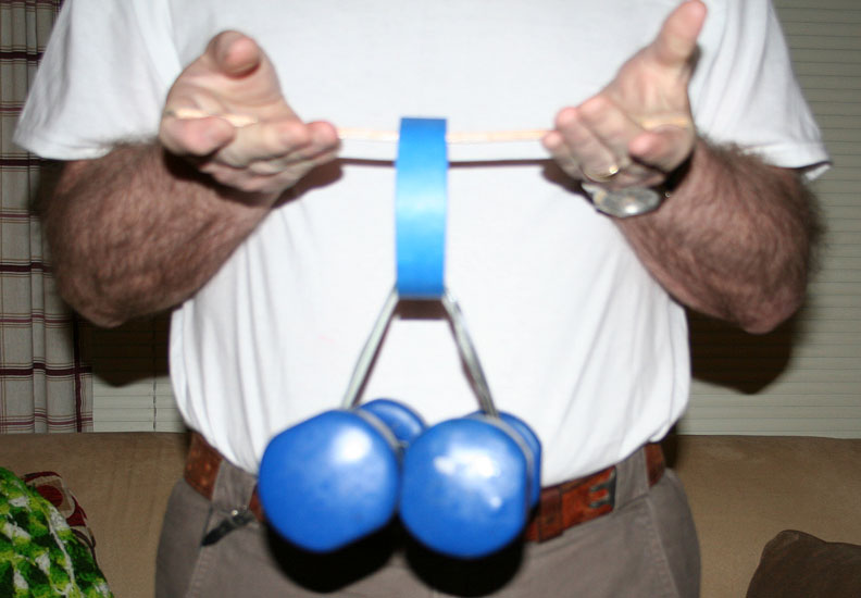
Getting my fuselage to support the pull test, I have made a test specimen for my longeron design by using a 3/16 t. balsa stick. I glued carbon fiber strips that are only .007” t. to either side to make the chords of the beam. The strips are glued on first with medium CA glue and then finished with thin CA along the edges to ensure no gaps. I have included a couple of pictures of the stick and it is supporting 10 pounds of weight.(No, thankfully, it only may appear that I have taken a hit where you don't want to…) (That picture is strangely out of focus, sorry.) It has not been tested to ultimate strength. It does not by itself have to support the whole pull test as other members, the stringers and skin, will take the rest handily.
Now comes the cool part: an I-beam's strength goes to the moon as you increase the separation of the chords. If you have the room to double the separation, the beam is eight times stronger. If you can triple the separation, it is 27 times stronger. The strength for this situation depends upon the cube of the separation. The strength just goes straight for “trans-lunar injection.” If you have room to also widen the chords, the strength depends upon the fourth power of the dimension. In my case, now, the longerons getting the CF straps for chords are I-beams that are laying over on their sides. The bottom chord of the beam is now on the outer surface of the longeron and the top chord is now the inner surface of the longeron.
Case in point about the strength of beams would be the temporary bridge up at Burlington, Wash., last summer. It was a military Bailey Bridge, which, as you may know, is built up from a basic element like Legos. If you stack two elements one atop the other, you have doubled the separation of the chords and the element is eight time stronger. If you then add another stacked pair along side of these, everything all fastened together, thus doubling the width, the span is 16 times stronger than a single element. The diagonal webbing between the chords of each element is actually mostly air; the braces are usually angle iron (steel) crisscrossing each other.
In my cockpit area on the F-84, the side longerons run just at floor level. There are the left and right control consoles at either side of the floor. These side consoles allow me to greatly separate the chords of the longerons, which become the floors of the consoles. My longerons are not restricted to 3/16 sq for the webbing. By the time my webs are 1/2” wide, having my .007” t. carbon fiber chords, they could support the pull test of a D-Class Speed plane, I think. At a half inch width, my longerons will be 18. 9 times stronger than the 3/16” sq. beam shown in the picture. This comes at scanty weight gain. The picture shows the skinny beam supporting 10 pounds. 18.9 times that is, well, a huge weight. At some point getting there, the possibility of exceeding the shear strength of the balsa web or the shear strength of the medium CA glue bonding the CF strip to the balsa could occur. I have not taken time to calculate what the ultimate strength is for this. You should make your own test article and try it in your own hands.
Flying Lines home page
Back to Scale Matters column main page
Back to Scale main page
This page was upated Jan. 10, 2015


