![]()
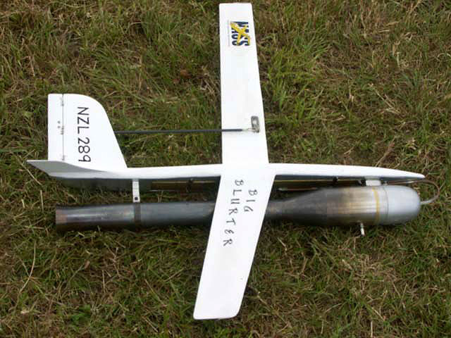
The record-setting TARFU jet speed plane by Andrew Robinson of New Zealand. Photo provided by Ken Burdick.
Yes Folks, it's true.
There is more fun in the anticipation of something than the actual doing of it. Getting married, that new car, and yes even flying the new TARFU.
As promised, I am sending out the update on my attempts to fly it which was tried just over a week ago in Portland Oregon. I had some of the best assistance one could ask for. Dick Salter brought his equipment and jets because we all needed to learn how to use the new fuel which is more like glow fuel without the oil.
Another speed GURU was in attendance and it was none other than “Jivin Jet-Louie” from the Louie-Louie Jet Team and the Buzz Man from our very own Broadway Bod Busters. (The hits just keep coming don't they?)
I'm getting to that.
Well, As you can see from the pictures, it started out white, fairly clean with one major flaw, the tank vent. From the pictures of plans and no good experience, I had used the pressure vent size and not the suction vent. The engine would only run as long as Dick put his hand over the intake to increase suction. Jivin Jet-Louie advised me that Dick was too old to run around the circle like that and to change the vent.

The vent size was increased and mo attempts were tried at the NW Regionals. The results of this was a great spitting of fuel out the front end with each burp. Now, I don't know much about jets, but at that rate, Salter was sure to be set on fire trying to start this thing. We elected to go get a hot dog after an hour or so of fiddling with it.
Like Yogi said, “half of Baseball is 90% wrong”
(Enter the Buzz Man, The BBB's Legal mind and source of generally good suggestions.)
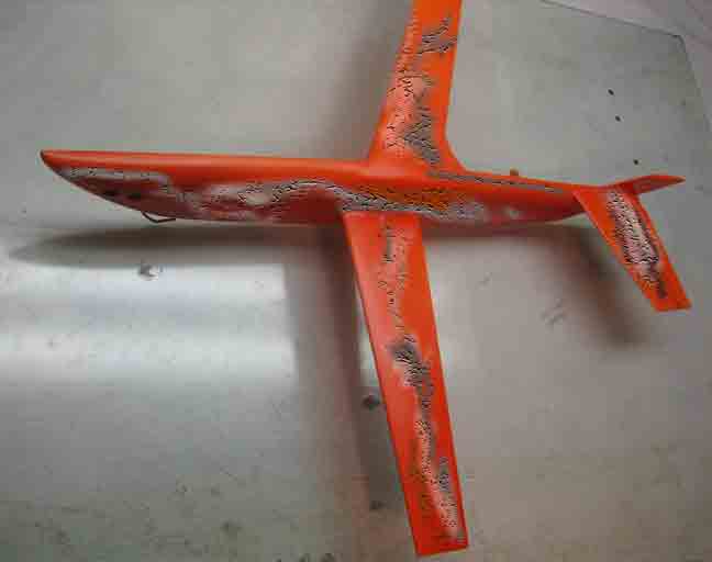
“I can paint that and It'll look better” he said. It's true that I do not have a spray system and had used rattle can paint and primer. Not a bad job, but not close to what Buzz had been doing with his set up and the preferred epoxy paint. “Sure!” I say and hand him the yet unflown TARFU. Can you do it before the Regionals? I ask. “I'll let you know” he replies. “Do you want it Yellow or Orange?” “I don't care, whatever works for you ”,I was very grateful for getting a real paint job!
It's been said before and bears repeating…….
Som eplace there is a finish compatibility chart, I think I'll send it to the Buzz Man. While intensions were good, the once less than ugly TARFU underwent a morphsis, like a caterpillar changing into a butterfly, more like a maggot turning into a fly.
Lacquer thinner was used in the Epoxy paint so it can be sprayed, it attacked the unsuspecting TARFU and in moments transforming it into a mass of bubbling goo!
It appears that I will have to fly it this way at the Regionals, I'll plug up as many of the paint holes as possible……stupid tarfu……stupid paint job……I hate everything…….
Stay tuned to Flying Lines for the continuing saga of the TARFU.
T.A.R.F.U.: Things. Are. Really. F'd. UP.
 The TARFU is a jet speed plane that that like most models is a combination of several others, but this combination of the ideas was applied nicely and with results that keep paying dividends.
The current world record for Jet Speed was set in December at 205 mph, then reset at 206 mph. Andrew Robinson of New Zealand recently set a new mark of 211 mph! All used the TARFU. He also attended a recent contest in Whittier Narrows and beat the best in sport jet a two-line TARFU.
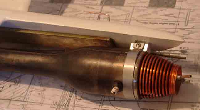
That being said, the pulse jet is a most interesting engine. I'm not going to even begin on what I think I know from reading about them. What I can say is they are sensitive to how they fly and if they are lean or rich. The current engine in favor is the ones produced by Jet Bill. He makes a sport and a fast version. I believe they hold all current records.
Okay, why is the TARFU any better than say a Super burp that ran 211 in the 1970s or some other oldie model that has run up record speed. Good question! The best answer is that it addresses many ideas and dynamics of other models where they may fall short. The same speeds years ago cannot compare to today's as line size has increased radically and fuel components have been restricted.
 Credit where credit is due
The fuselage and fuel tank is basically a sidewinder and credit goes to the late Mike Hoyt for his Sidewinder design.
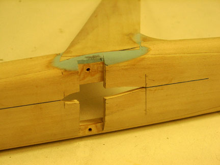
One major issue with the pulse jet is the tank, it's relative position to the engine and a host of dynamics I don't fully understand. The long thin rectangular tank reduces the rich to lean tendencies that pulse jets are so sensitive to. The tall chubby looking fuselage holds the 12" x 5/8" x 1-1/2" tank in a window of the profile of the fuselage.
The wings -- I wish I had an answer but like the man in the balloon said, "I don't know how it works." What I can show you is the answer to my question posed to originator Glenn Lee, (ol Blue) about why it works. Here is what he had to say.
Ken,
I built that swept-wing B job back about 1954, and also a swept-wing A job. I have no idea why, but maybe because we had to hand-launch everything back in those days. These models are super stable and fly beautifully. You have to balance them by assuming the wing chord average is a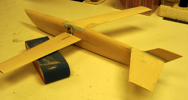 t the point about 1/3 the distance from the fuselage to the wingtip, and balance about 1/5th from the leading edge.I built an asymetrical speed 15 FAI job many years ago. It "floundered" around the circle!! Purely unstable! when I built the jet plane with the inner wing on center of thrust, I added the swept-back top wing just for a stabilizer. It worked, now everyone uses the same idea. The model flies where ever you want it, can't believe the stability.
Glenn
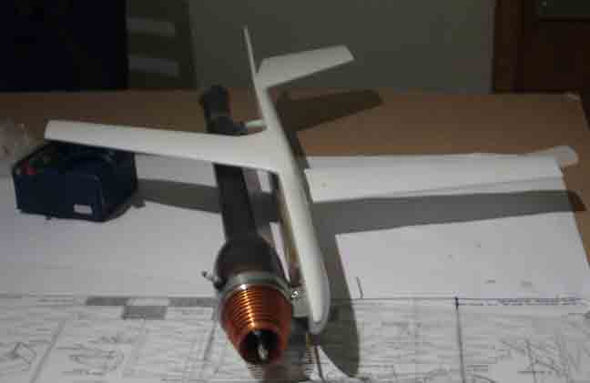
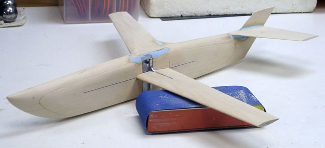
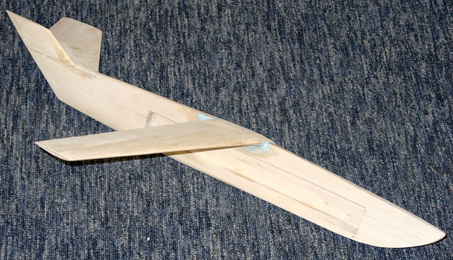
How's that for a little history? The inboard wing is placed on the center of thrust line of the fuselage. The engine on the other side of the body is centered on the same line. The leading edge of outboard wing is at the same distance from the nose as the inboard wing, but is swept back at 28 degrees and is on the top of the model. So, we have one wing perfectly inline with the thrust line and the other on top of the model! My head hurts -- what this does, dear readers, is to keep the jet flying very low and stable. A jet will slip off much speed if it hunts or is given constant control to stay in a groove.
So Hoyt made the fuselage/tank in 1971 and Glenn Lee made the wing arrangement in 1954. When I look at this sort of thing I wonder to myself if I've ever had a good idea.
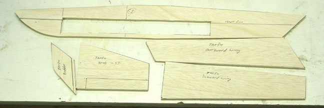
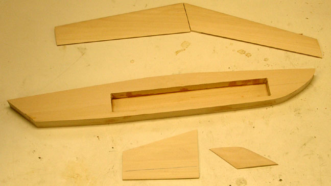
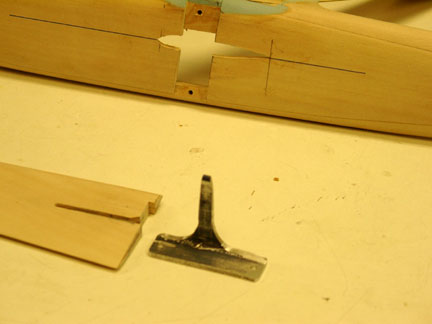
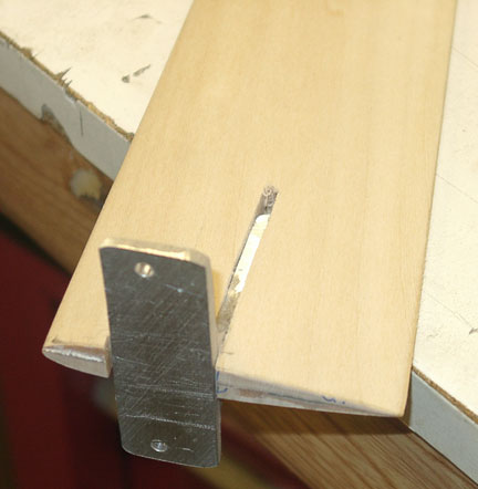
 The plans as shown leave a bit for the imagination, but with enough study you will find that a slab of 3/4" basswood is needed as well as some 3/16 bass. I purchased mine from National Balsa at decent prices. Ask for the whitest bass wood as it will be lighter by far. The wing bracket as shown in the plans (sketch) is for the Fast model, the bracket I made is for the sport jet model only. There are many ways you can attach the inboard wing, but remember the engine and all must take the pull test, not just the wing and fuselage. Fortunately, a sport jet at best is about the same as our old days rat racers (140-165 mph at 35 oz). The bracket I fabricated is 6061-T6 aluminum 1/8" thick. This can be found at On Line Metals at a pretty low cost.
I made a set of templates for all parts and included the thrust line markings on the template for the fuselage. I have sanded off and redrawn it several times during the construction on the actual model. The wings are made of two thickness of 3/16 bass with thin carbon tape laminated in-between. I use a laminating epoxy (finish resin) from the local boat store, it's expensive but worth it. The stab and tail are also made of 3/16 bass. An interesting feature of the tail fin is that the curved side is on the outside. At higher speeds, it will tend to point the model in at you, this was something that Mr Hoyt wrote about and challenged the speed flyers to experiment with. The idea being to get the model to fly more in a circle than pointing the nose out for line tension. Hoyt believed that the jet would get better airflow through the head than if was at a tangent to the air by pointing out more.
 Due to the thick wood and lots of carving, purchase a decent finish plane and use a good belt sander. A hand sander can be used but it will take awhile.
The fuel tank was made out of .007 brass shim that can be purchased from McMaster-Carr. I purchased a metal brake to fold the long thin tank as the tools I had were not up to the challenge. Do a few trial folds on a piece of paper before attempting this one. Once you are comfortable with it you can make this bad boy in no time at all. I glued a piece of graph paper to the brass and folded it on the pre drawn lines I had made. The Buzz Man uses a glue stick and the paper comes right off.I however used 3M 77 and it didn't, so get a glue stick.
The primary tools for construction were a band saw, finish plane, sanding belt and a good hand sanding block. The TARFU is fairly easy to build as long as you reference all positions from the centerline of thrust. That means wings, stabilizer, tank hole, bracket placement, engine mounts.
Good luck with yours, I'll let you know how mine flies.
Kenny-b
 Sources:
Bass Wood: National Balsa
Bracket material: 60601-t6 One Ft. (12") Length - $3.28 -- On Line Metals
Tank Material:
007 brass shim stock -- McMaster-Carr.
.007 x 6" x 60" Part Number: 9504K21 $9.19 per roll.
Metal forming brake --Item # 82817, $38.55 --MicroMark
By Lenny Waltemath
Front of tank is located 4" from nose. Top of tank can be no higher than 1/4" above thrust line. Any higher and fuel will siphon into engine making for hard starting and many burnt fingers. Engine placement is nose of engine even with nose of aircraft. Combustion chamber is 3/8" from outside of tank. 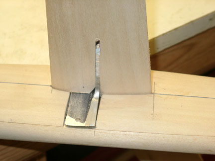 Engine mounts, your choice. I use the old hose clamp set-up on the sport jet front mount. This allows for some forward/aft movement if desired. On the fast jet, the Bailey mount is fine. The old Hoyt mount works well also. (Bolts in fuselage, nuts inside cowl.) Rear mount, standard operating procedure. Just remember the engine and pipe have to survive a pull test too. Construction of my aircraft utilizes ALL basswood. My ships consistently come in 3 to 4 ounces lighter than my competitors. The secret? Chose your wood. Buy only the lightest, whitest basswood you can find. By this I mean the color of the wood. The whiter the color the lighter the wood weighs. A really white colored piece of basswood is about the same weight as a comparable, same size piece of hard balsa, yet is three times stronger! This, along with the use of carbon fiber strips and cloth in some areas will give you a lighter ship than most of your competitors.
FOR THE CENTER OF GRAVITY: Place your fingers on the leading edge of each wing, right next to the fuselage. The aircraft, complete with engine, should point nose down 30°. So to attain this, the leading edge of the inside wing at the fuselage is about 9 1/4" from the nose.
THE CONTROL UNIT PLACEMENT: On the sport jet using a 1-3/4" Formula .40 bell crank. The pivot point is 13/16" from the leading edge.
BUTTON PLACEMENT ON THE FAST JET: Is also 13/16" from leading edge.
LEAD OUT PLACEMENT AT WING TIP: Is up to you. (1'm still experimenting and don't know.)
 Well that's about all I can give you guys. Build your ship as clean as possible. Remember, a jet is pushed through the air and prop wash covets a lot of ills. We don't' have that luxury.
KEEP' EM CLEAN!
Best & Fast Times
Lenny
Notes on The TARFU Sport Jet
By Jim Rhoades
The Morris bellcrank is held on with a 6-32 Phillips head screw that is locktited in. The pushrod originally was brass tubing with wire ends. I changed it to a 1/8" carbon tube with wire ends as I had some cracking in the brass tube that I attributed to elevator flutter caused by pushrod flex.
The tank on the plans is for the fast jet. The sport jet tank is about 6 oz. It measures 1 _" tall x 12" long x 5/8" wide. I compaired the two models at a contest and the Sport Jet is 1/8" narrower and 3/8" to _" skinnier in the vertical dimension of the fuselage.
The stab on the sport jet is not swept as much as the fast jet.
(The sport jet stab is shown in the sketches.)
This page was upated July 15, 2010