![]()
A View from Broadway
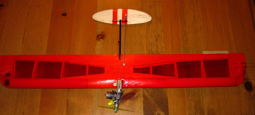
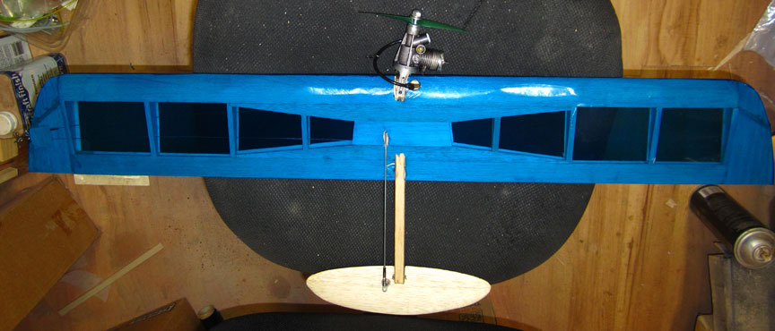
The 1/2-A Monoboom ready to fly. All photos by Ken Burdick.
1/2-A Monoboom building notes
By Ken Burdick
November 2019
This article follows up on Ken's original 1/2-A Monoboom article from 2018
Yes, Folks, it’s true.
I usually try to entertain as well as inform just because these hobby articles can be so very dry. This isn’t one of those times. Listed below are notes I put together for good buddy and Bod Buster Buzz Wilson aka The Buzz Man. What you see before you are the down and dirty things I discovered in making the 1/2A Monoboom something that would take the rigors of today’s super-fast engines, the occasional deep dive into the earth, while still maintaining its original outstanding performance. I have included pictures that really apply to a builder’s eye, for the detail they show.
I’ll entertain another day, but if you want to build one of these rockets on a string and use it with today’s modern engines, here’s what I did. This assumes you have 1/2A Monoboom plans, that can be purchased from Bob Mears, who is maintaining the plans service formerly sold by Barry Baxter.
Weight: Due to the small wing area, weight becomes important. Too much weight savings resulted in a weak model so the spars and leading edge are made of spruce.
Selected balsa is also used. The key areas are the braces (not shown on the plans) but are on the full size monoboom. This and the center section planking are key to it’s being able to take a crash.
Cap strips are another feature that help in its strength, They are a pain, but well worth it.
When I used hard balsa here and there, the weight gain was significant so I now use a combination or contest grade and hard, it seems to work the best.
Trailing edge: I make the T.E. pieces 1’ width only to the point where the tapered center brace end. From there the T.E. tapers to 3/4” as per the plans. Use hard balsa for these tapered braces; they are spars. I attach them to the T.E. before assembly. Make the bottom T.E out of medium-hard balsa; make the top out of soft-medium balsa.
Spars: Use spruce 3/16 x 1/8. Leading edge spar is 3/16" square. This will eliminate the need for vertical braces shown in the plan set. Spruce can be purchased from Aircraft Spruce. I found that they needed fine sanding before use.
Center sheeting spars: (Not shown on plans) This is shown only on the full size M-boom. It is a VERY good idea. I make mine from 1/16”x14” x 3/4” that taper to 0 two inches from the center on each side. There are four of them.
Ribs: I make my ribs out of medium grade; light wood is just too fragile.
Planking: For the L.E. planking, I used contest grade light wood 1/16” all the way. The center section should be medium weight. The leading edge planking has to form on the outside of the L.E. spar so be sure to soak the balsa planks.
Capstrips: Light balsa only. The weight gain was too much using anything else.
Wingtips: This is a key part. The way they are shaped makes them suspectable to covering warps. Plywood strips on the rear part is suggested by the designer (Velum on the large version). I did that and it was still an issue. Now I use the hardest 1/16" balsa I can find, usually nondescript Balsa USA 1/16”. It looks like old Sterling kit wood. This will save you lots of other problems as well.
Fuel tank: Put the fuel tank on the outboard wing.
Fuel tank area detail.
The M-boom was designed back when TeeDee engines were used and the tank capacity is low. Partially due to the smallish spar distance from the L.E. and partially due to the thin airfoil. For this, I suggest adding a bulge to the L.E planking. I cut two circles of balsa wood and glue them at either side of the tank area. It’s more work but makes the tank more practical. On the originals, I didn’t do this and had to use thin surgical tubing for a bladder, nothing else would fit. To make the bulge, I use a 1-¼” hole saw to make the two disks of 1/8” balsa, and then notch them for the leading edge, and trim it so it will fit between the l.e and wing spars.. Also carve down the point of the L.E. spar inside the fuel compartment as it crowds the bladder space.
Booms: The booms are made per plans, but use soft-med balsa and epoxy the ply sides to it.
Elevator: Use 3/16" LIGHT balsa. I buy my contest grade light from Stunt Hangar. Fair price, great quality. Do not skimp on this, use and shape the 3/16.
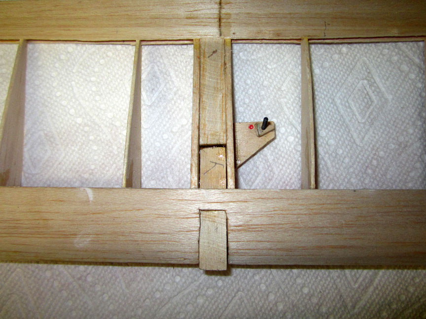
Hinge: The Goldgberg flex point hinge will NOT work. It’s shown as an alternate in the plans. It will not take the speeds your engine will provide, and you will get stab flutter.
Here is what I use that works with no vibration or flexing:
HINGE BEARING. McMaster Carr # 105c004025. 2 ea per boom.
CA glue to the drilled-out boom and CA in place. Once dry, drill out to .135 for a carbon fiber rod .125 dia or tube to be used as a bearing rod; mine are 2” long. You may have to shorten the length of the bushings so they don’t run into each other inside the boom.
Control horn: Use a low grade 1” long 4-40 machine screw. I cut 1/64" plywood disks with a sharpened piece of brass tubing. Glue them to the elevator. The bolt is run through the plywood with washers and nuts. Be sure to add Locktite. The control horn itself is a Du-Bro # 557. 3/32 E/Z Adjust Horn Bracket for 4-40 thread.
Wingtip weight: Use 11 grams or 3 pennies.
Trim Tab: Make from pop can material and Gorilla glue to a 1/32 x ½” piece of plywood. Allow 1/2” of alum into the T.E. or it may fall off. I use white glue for this after the model is covered.
Leadouts: The first leadout should be 2.5” back from the leading edge. Space the down line 1” back from there.
Wingspan: The outboard wing is 1” shorter than the inboard. The total span is 34” with a 5” chord.
C.G.: Locate where the plans show.
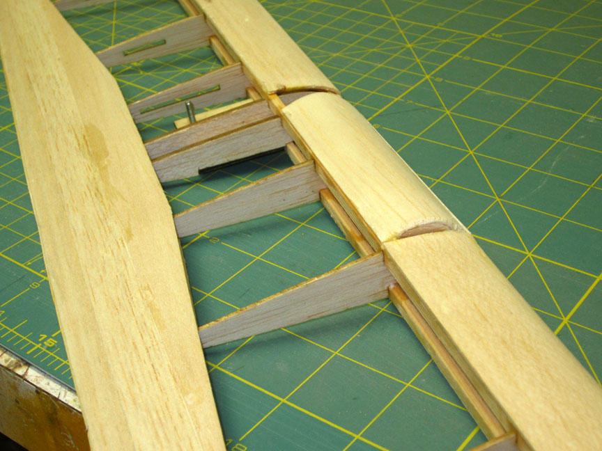
Engine Block: Make as you see fit. I use 1/4” 5 ply x 2. The height between ribs on my wings is .703, under the spars, so the part extends back into the wing and is notched for a bellcrank platform. In front of the spars, the size is reduced to .538 for a Combat type mount. I use one hole for the engine mounts. In the case of a crash, it will pivot and not break the mount block.
Covering: Covering isn’t one of my joys in life. I use Ultracoat from Horizon Hobbies. I have recently purchased some rolls of Hobby King covering which is about half the cost and looks pretty good.
Weight: The all wood model should weigh in between 120-140 grams depending on the wood used. A lighter model can be built using all balsa for the spars, but will not be as strong.
Flying: The 1/2A Monoboom flies as well as any 1/2A Combat wing I have flown to date. If built right, it will not hunt or over-turn. The elevator movement should be no more than 15 degrees if the model balances on the CG shown on the plans.
This thing is really high-aspect so it’s not for beginners or the faint of heart. Hold it dead level for the first quarter lap and let it bounce around. If you give it control input or jerk it, then it’s “game on,” and I wish you luck. The model is especially tight-turning without much speed loss; the faster it goes, the better it likes it.
-- Kennyb
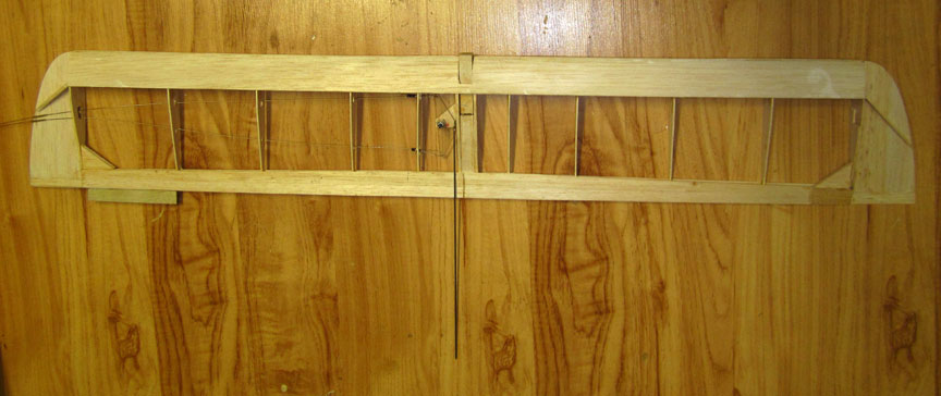
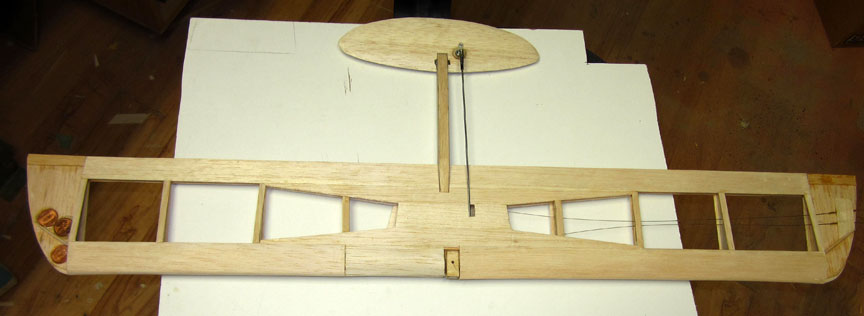
The 1/2-A Monoboom wing framed up.
Engine mount platform detail.
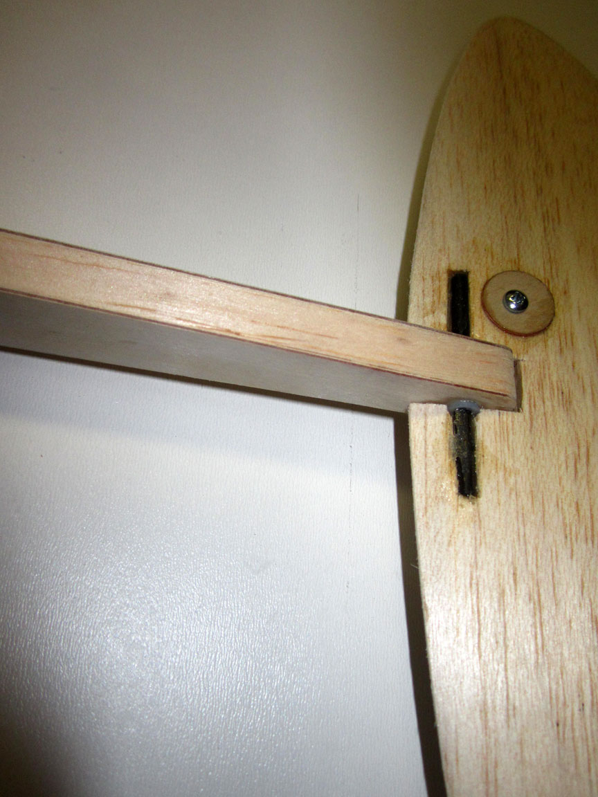
Elevator hinge detail.
Ready to cover at 97 grams.
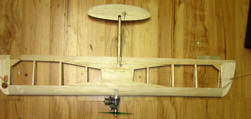
Engine test mounted before covering.
Engine offset assures tight lines.
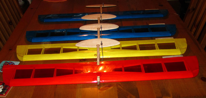
A batch of 1/2-A Monobooms ready for action.
Back to Bod Busters main page
Back to Combat main page
Flying Lines home page
This page was upated Oct. 30, 2019