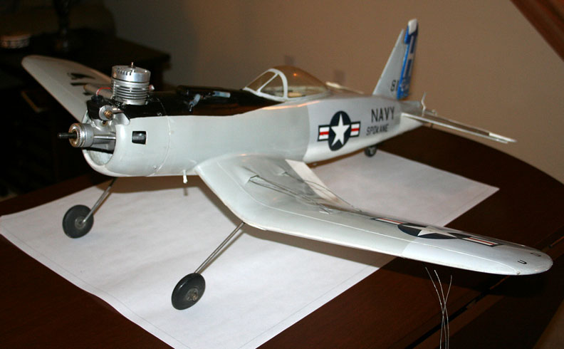
Orin Humphries has been building, flying and writing about control-line model airplanes for decades. This is his "Hawg" Corsair for Navy Carrier. All photos provided by Orin Humphries.
Basic control-line building
By Orin Humphries
March 2014
A recent issue of Model Aviation had a couple of pictures of models that caught my eye. Each had a really basic building error that apparently needs to be mentioned again for newer people.
The first one is a Profile Scale B-29 and it is nicely done overall. In the photo of it I am unable to see a pushrod brace for the long rod back to the elevator. Let's say for the purposes of this article that the model in fact does not have one. Many years ago when I was leading the Spokane U-Control Club, one of the men asked me to test fly his brand new profile P-51 from a Sterling kit. I declined strongly as experience had brought me to do. However, he would not be deterred until I flew it.
Everything was fine until I did an inside loop. The loop relaxed at the back end resulting in a crash. Remember? We used to call that “re-kitting it.” Oh, great! This was why I don't fly other people's airplanes. He was very unhappy, of course, and it took a bit to discover the cause. I finally spotted the absence of a pushrod brace on the fuselage. When you are feeding in full UP, the pushrod usually is pushing back on the elevator horn if the horn is under the elevator. This places a compression load on the pushrod. The rod at some point buckles from the high load and lets the elevator relax toward neutral. Some form of brace on the rod at the midpoint will greatly reduce that and save your bacon many times. Don't' go to the flying field without them!
Pushrod brace/guidePushrod brace/guide
First, a pad made of 1/64 plywood was glued onto each side of the aft fuselage to brace the pushrod guide soon to come. I bent a length of .030/.040 wire so it looked like the back end of a safety pin and stuck it into the pads on the sides of the fuselage for profiles. In one photo below you will see I sometimes used a Cotter Pin. If it was a built-up model, 1/8 sq. stringers across some gap in a former at mid-pushrod would do.

Pushrod guide on Orin's Shoestring keeps the rod from bending.
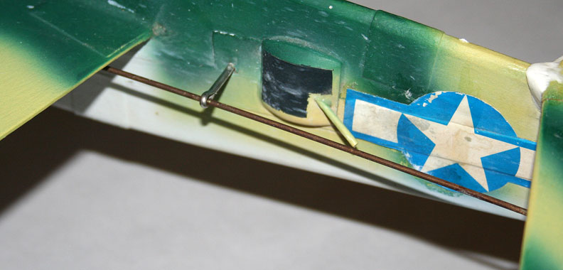
A cotter pink works well as a pushrod guide. This one's on his profile B-25.
Leadout exit
Another model with a basic problem in the recent issue of MA was a P-38. The builder had brought out the leadouts at the wingtip. On airplanes like the P-38, F4U, B-25, etc, the wingtip is above the vertical location of the plane's CG. People make their leadout exits at the wingtip because it works on models with midwing designs. They don't think about it. What happens with a high leadout location is that the model when flying is rolled in on you. Your line tension is weak and you are susceptible to having the airplane blow in toward you on the upwind part of the circle. Corsair pilots universally complained of this.
B-25
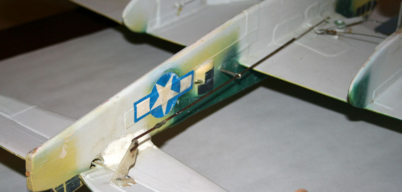
In the accompanying photos you can see the pushrod guide on my Shoestring Stunter and a Profile B-25 I built for my son. The B-25 is getting refurbished after its active career. You will notice that the B-25's bellcrank is mounted ahead of the leadout guides that pierce the nacelle. That doesn't matter. In the photo where I am hanging it from its leadouts and it is nose-toward-you, note that the outboard wing is closer to me than is the inboard wing. In flight the model would be rolled outboard like this for better line tension. “How it hangs in your shop is how it sits on your lines in flight.” In the photo looking at its top, note that the nose is lower than the tail. That means that in flight the model would be yawed away from me, again for line tension. Yaw setup like this as you will recall is also called, “rake angle.” These angles are totally determined by the leadout exit location.
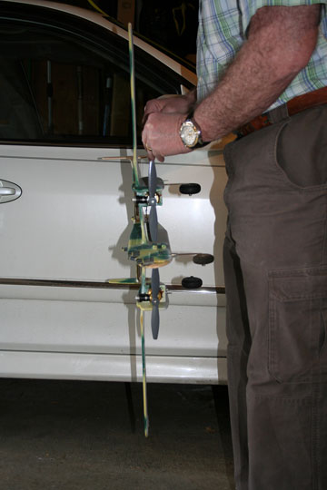
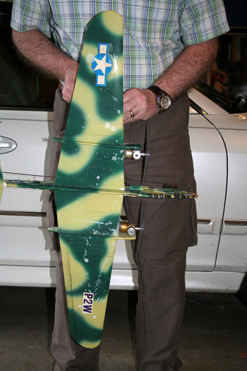
Roll angle (left), yaw angle (right) and the pushrod system (below) for the B-25 under refurbishment.
Corsair
I nicknamed my Corsair the “Hawg.” It held the record around here for a while. On my Corsairs, the leadouts emerged from the bottom of the wing a good three wing ribs in from the tip. My A-26 had a wire frame leadout guide suspended below the tip tank. On my soon-to-come F-84, the guide is projected to emerge along the bottom of the tip tank. It was frequent that other Corsair pilots had their birds torque roll in on them on takeoff because their leadout exits were on the wingtip, too high. How do you tell where to locate the guide? Easy.
Leave that detail for last, putting off skinning the inboard wing if necessary. The model must have all else on it for the test even if only taped on temporarily. First hang the model from its leadouts with the belly toward you and the nose to your left. Grasp the wingtip and rotate the model about its yaw axis until the nose is just a little outboard (if it was actually flying), seen as below level, here. Mark that fore/aft location for the guide. Now turn the model while hanging from the leadouts so its belly is toward you. Rotate the nose a bit until it is below level as in yawed away from you if in flight. Mark that location. You now know the place to put your leadout exit!
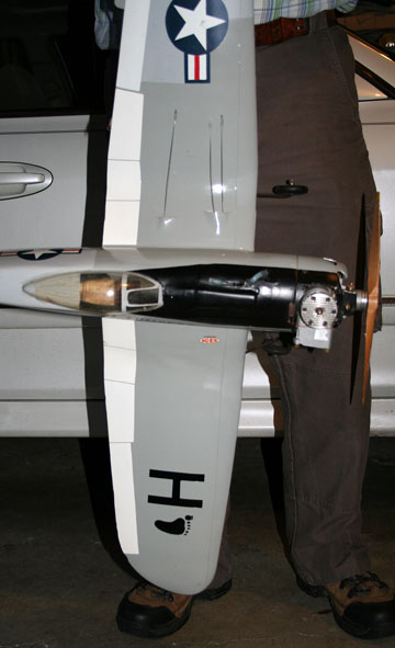
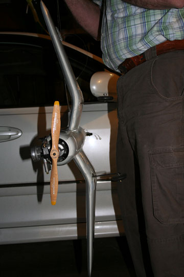
Orin demonstrates checking the yaw (left) and roll of his Hawg.
Never just assume. Always check this. You will be saving your model some bad day when your engine hiccups on the upwind side of the circle.
In the photos of the Hawg, you note that the wing is rolled outboard. This is because as said above that I found the correct leadout exit location to be the third rib in from the tip. This model would have even more outboard yaw, now, if the muffler were on it at this time.
Shoestring
Again you see my pushrod brace on the aft fuselage. If you look at the underside of the wingtip, you will note that I did NOT bring the leadouts through on the mid-line; they emerge halfway between the midline and the bottom of the rib.For this model, I thus get the good outboard roll angle that you can notice in the photo of it hanging from the leadouts.

Leadouts exit the Shoestring at the bottom of the wingtip. Correct location will vary based on the airplane design. Testing provides the answer.
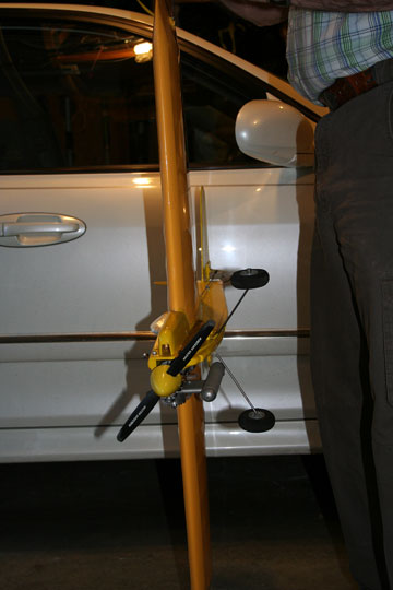
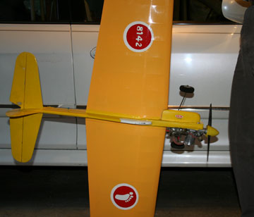
Next, while still hanging it from the leadouts, rotate the model so the nose is pointing toward you. Grasp the wingtip and rotate the model about its roll axis so it would be rolled away from you slightly if it were flying. Both of these angles are necessary for proper line tension. On your lines while airborne it must be nose outboard and left wing high. Physics works for us here, in that how the model hangs on the leadouts in your workshop as is described above, is how it will be on your lines in flight. Further, it really doesn't matter where you locate your bellcrank, fore and aft, due to physics. That is beyond the scope of this short article, but trust me on this. It is all determined at the leadout guide.
Flying Lines home page
This page was upated Feb. 26, 2014

