![]()
A View from Broadway

The new TARFU, with the trimming fixture described in the article protruding from the front and rear of the engine. All photos by Ken Burdick.
A fixture for the TARFU
By Ken Burdick
January 2021
Yes folk’s it’s true.
TARFU: “Things are really F’d up”. The guys down under have great luck with them, me not so much.
Recently I dragged out Mike Hazel’s jet pack and read all the many articles again. The trial and error in them is tremendous. What I was looking for was trim of the flying surfaces to the thrust line. I found a taste of it in Jerry Thomas’s article published by Speed Times October-December issue 1991. Jerry was a record holder at 206 mph. That’s pretty fast for a blowtorch. Back then the fuel was considerably different. One gem I picked up in the article was a note about Joe and Dale Kirn running their jet in 1987. They ran 205 at the Lincoln, Neb., Nationals. Dale said they trimmed the model by adjusting flying surfaces .005 at a time. This really hurt my head as I looked at my sturdy epoxied TARFU. How on earth would that be possible with this model? How would I even be able to measure such a thing relative to the thrust line?
When in doubt, ask the experts, right? I posted a question about this on Facebook “world order of control line pulse jet fliers.” This is where the guys all hang out, and I was sure I would get some info. (Cue the cricket noise.” Not a peep. So I let it go and when I built my model, stayed as close to the thrust line as was possible. Still, the problem was there and evidenced by a few models that were faster than a TARFU style without explanation. I suspected flying surface gremlins since the same engine was used. In all fairness it may have been the tank as well.
The problem of how to measure the TARFU wouldn’t leave me alone so being sequestered as we all hopefully are, I didn’t have flying to distract me. So, I came up with this fixture.
Things are round and the airplanes all wonky!
The fixture relies on a centerline through the middle of the jet. I machined a plug that is a tight fit into the tail pipe with a centered tapped hole and a ½” diameter rod attached to it. The rod is also drilled perpendicular to slide over 5/16” piano wire. The assembly has a lock plate that works as a jam-nut when it’s in its final position. A simple wheel collar is also used on the back of the jig to adjust the height of the tailpipe so as to be level with the head as seen side view.
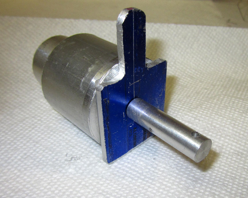
The rear plug.
The front of the engine was simpler. The flowjector is centered in the head of the engine and tapped 10-32. A ½” rod with a threaded insert will make a guide for the front. It too has a perpendicular hole drilled in it to slide over a 5/16 piano wire.
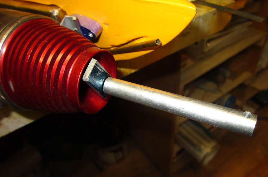
The guide at the front of the engine.
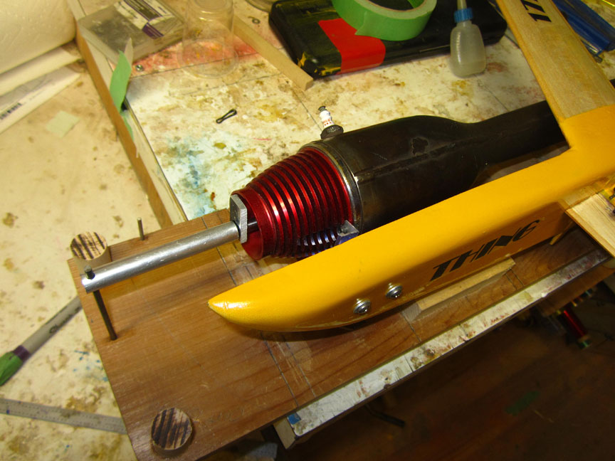
A wooden platform was fabricated with blocks for the head to rest on. I used an old 1/2A Monoboom jig to make this platform. The piano wire was carefully located and installed and the front and back fixtures in place. The engine (with model attached) was lowered onto the vertical 5/16” rods. The front of the engine was measured from the top of the jig to the center of the front ½” rod extending out of the nose. Next, the rear of the jet was adjusted to the same height, and the wheel collar locked to keep it at that location.
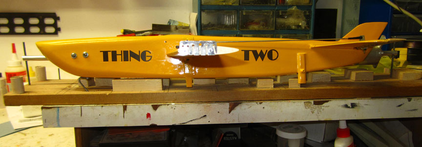
Side view.
We now have the engine level. The wings and stab can now be measured from the top surface of the jig. This will show us if the wing(s) or stab are at a tangent (up or down) to the centerline. This is where pulse jets respond to the slight variations to trim.
All this sounds good, but the proof is in the flying. We’ll see when we all get together again someday.
Stay safe, geezers.
-- Kennyb
More photos
Front view.

Another look at the rear plug.
Back to Bod Busters main page
Back to Speed main page
Flying Lines home page
This page was upated Jan. 19, 2021