![]()
A View from Broadway
Reworking Boris:

By Ken Burdick
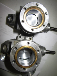
Boris was interesting to me from the beginning, who knows why. The parts seem to be well made, not Henry Nelson well made, but adequately. The overall fit was tight so some fitting was in order. To begin with, the front end was tight, induction drum just OK, and the drum to drive pin was tight. All this can be corrected through running for the most part but we want it smooth and free before fuel ever gets involved.
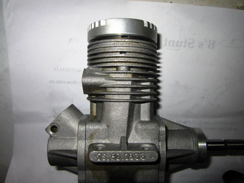
Boris before rework. All photos by Ken Burdick.
Crankshaft
I want a firm but not press-in fit of my crankshaft to the front end, so some polishing would be in order.
I made a fixture and using my drill press, pressed the crank shaft out of the housing. The crank was polished with 1200 grit and emery cloth until it could be assembled into the housing, tight but not needing heat to assemble. I do this by taping the threads and spinning the crankshaft in the drill press. The same was done to the induction shaft with a fixture that was pressed into the hole and once again, spun on the drill press.
An odd polish was the drive-notch cut into the face of the drum rotor. I made a polishing tool out of 1/16 wood and wrapped 600 emery around it. I polished the inside of the notch until it was smooth, then lapped the face of the drum disk on 1200 and emery.
Something interesting jumped up when I reassembled Boris into a conventional exhaust pointing back orientation, the engine comes assembled opposite with the exhaust stack pointing forward towards the crankshaft. The piston has a notch that I assumed was for fuel flow, what it also does is to provide a relief so at BDC the piston skirt will not hit the rotor drum housing, when I assembled the engine with the piston notch oriented as before, it bottomed out against the drum rotor housing. This could have been solved by notching the piston, but I chose to mill a small flat on the rotor housing.
Correction
The conrod does in fact have an oil hole on the top, but not on the bottom. I added a 1/16” hole and deburred the rod bearing. One nice feature is a grooved bronze bushing at the bottom end of the rod. With the fuel entering the engine from the drum, it centers the fuel right at the conrod so we should have adequate lubrication there.
Piston and liner
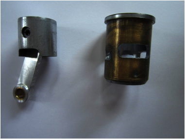
The piston and liner fit is very nice, however there are burrs where the ports are cut into the liner. Some special hand carving tools and a tiny diamond cutter used as a draw file removed them nicely.
So, front end…..check. Rear drum……check. Conrod ……..check. Liner….check.
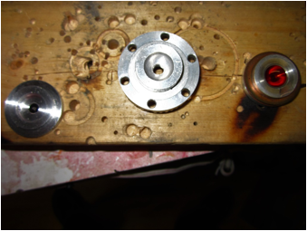
There are two very different heads for this engine. The aero
version (center) is pretty standard in that it’s a hemi dome and wide squish
band made to run low nitro fuels. The big surprise is the marine head, (left) It
is an exact copy of what Nick Shear published in Speed times 1985, (volume 4,
and correction in volume 5). This head was originally designed and used by
Frank Garzon and shared throughout the East Coast USA. The head was identical right
down to the .002 taper of the squish band, so someone was paying attention back
then. All well and good for running 70+% nitro, but we’re limited to 10% here, so looks like a trip to the head
shop is in order.
Head Volume
My current D engine (McGee .65) has a combustion chamber of 5cc, a squish band width of .160 with a .002 tapper.
The MDS aero head has a combustion chamber volume of 5cc and a squish band of .187 with a .001 or very slight taper to it.
The MDS marine head (Garzon copy) has a combustion chamber volume of 5cc a squish band width of .157 and a .002 tapper. True volume must include the squish area as well as the head clearance, this lil geezers, is where some of the fun comes in. Keep a journal, record bench readings and changes made to head clearance, as well as using the same reference prop. Remember, 10% nitro…..it makes the head a lot more critical than in the days of high nitro. I will begin testing with head clearance at .020 and go down to .010. The head that Richard Justic sent, was different still. A much wider squish band of .230 and a chamber volume of 3.5cc.
Nose, Nose, anything goes
One of the most irritating part of the project is getting a spinner assembly of some sort machined and fitted to the engine. It needs to be .65 in length from one end to the other…hmmmm. I tried Bill Hughes who sells OPS in the U.S. but he had no spare parts. Most people covet the little chunks of aluminum showing once again what a small community speed flyers are as parts can be hard to come by. Once we find a reasonable part, we can machine the length if necessary as well as adapting it to the crank diameter and lock cone. Lucky me, Richard Justic sent me his OPS converted spinner from his project! No work needed, it has been tested at 200 mph. Lucky for me, Richard Justic sold me his blown engine which included the spinner assembly! Meanwhile, I did track down the spinners that George Brown made. He sold it all to Dick Heart who promptly moved to Scotland……I was able to get in touch with Dick and bought two D spinners from him.
He sells A, 30mm; B, 11/4 inch; C/D, 11/2 inch. These are beautifully made and I recommend them. Contact Dick.
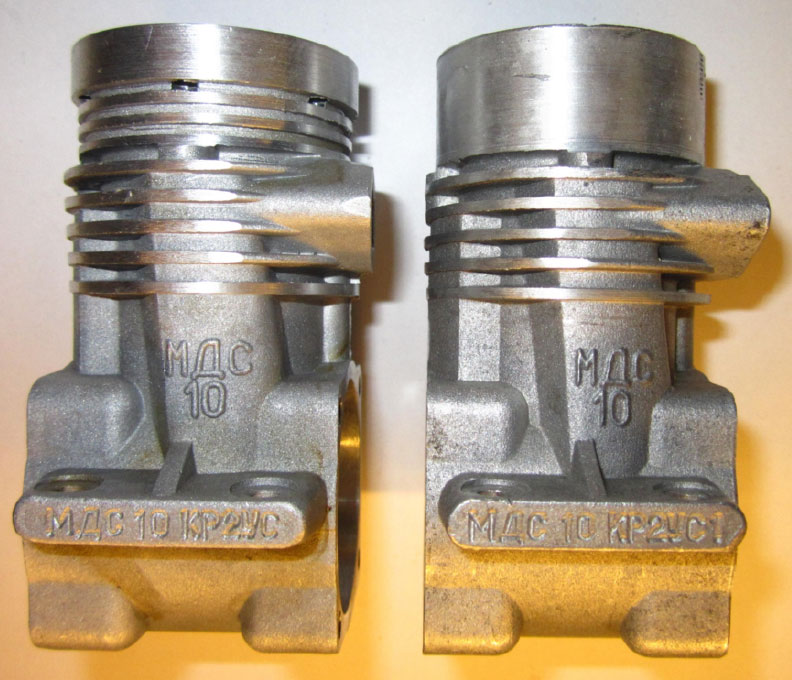
 Notice liner depth
difference.
Notice liner depth
difference.
The case size of the aero model is 2’ in diameter, and is a bit large for our streamlined Pink Lady…..what to do. Something around 1.80 would fit the cowling and crutch so machining a bit off the giant is in order. I began making a lathe fixture that uses the engine mounts. This caused all sorts of centerline issues that only a lathe (I do not have) could remedy. I took a break and rethought the problem.
I realized that I had a water jacket that bolts onto the marine as a head clamp. By turning it upside down, I have a grip for the lathe chuck and one that is centered to the engine. Fixture problem solved, and after a trip to Salmon Arm to visit Mr. Engine builder Greg Davis the machining would be a snap.
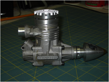
So, what was a bit fat was machined into
a case that would actually fit. In
machining both the marine version and the aero version, we discovered that they
are two different castings, not just machined for a water jacket, but two
separate molds entirely. Greg
turned the head and fins to 1.80, below the exhaust port, the fins were filed
by hand. The cooling system I use is the Bill Wisniewski “chimney” as shown in
Partner Products Excellent Pink Lady plan set. High pressure at the base of the
cowl and a suction at the top of the cowl, clearance around the engine allows
air up past the engine vertically and out the top of the cowling. Simple,
elegant and effective, but requires clearance.
Time,Time, see what’s become of me.
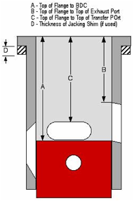
Well….after a not so accurate trip down memory lane with my
depth gauge, I was able to defeat the most useful program I rely on for timing
my engines. If you are not familiar with it, do yourself a favor. Find the timing program and use it. You simply measure the
piston height and it converts that into degree of crankshaft rotation.
I somehow got the port opening depth longer than the engine’s stroke, worse yet, I didn’t see it until it was kindly pointed out to me by the Cajun himself! I find endless ways to embarrass myself.
OK, so I need a bit of practice in not reading the depth gauge backwards I had given the program an impossible question to answer…..so it didn’t. Thus, my question “why isn’t the program working?”
Moving right along, the tables below will show the final rotor timing that I was looking for. The existing timing is a bit milder than that, so this is what I will make the rotor opening and closing as shown below.
On the lower chart, I have the marine timing. This is timed for a full wave pipe as shown by much higher timed ports. The liner is cut the same as the aero and it is the marine case that has it jacked up for the higher readings. Effectively on a mini pipe, this means a lot of cylinder charge will be lost out the exhaust port compared to the aero version.
Aero version timing:
|
|
||||||||||||||||||||||
![]()
|
|
Deck
Height
|
0.1940
|
Stroke
/ 2
|
0.4530
|
Rod/Stroke
Ratio
|
1.8720
|
Engine
Displacement
|
0.6102
|
Swept
Volume from Exhaust Closing
|
0.3744
|
Blow
Down (DEG)
|
22.28
|
Blow
Down (Inches)
|
0.1550
|
Exhaust
Port Values
|
|
Distance
ATC
|
0.5560
|
Distance
BBC (Port HGT)
|
0.3500
|
Port
Duration (DEG)
|
169.38
|
Piston
ATC (DEG)
|
95.31
|
Piston
BBC (DEG)
|
84.69
|
Transfer
Port Values
|
|
Distance
ATC
|
0.7110
|
Distance
BBC (Port HGT)
|
0.1950
|
Port
Duration (DEG)
|
124.82
|
Piston
ATC (DEG)
|
117.59
|
Piston
BBC (DEG)
|
62.41
|
Inlet
(Crank Port or Rotor) Values
|
|
Port
Opens ABC (DEG Crank Port or Rotor)
|
24.36
|
Port
Opens BTC (DEG Crank Port or Rotor)
|
155.64
|
Port
Close ATC (DEG Crank Port or Rotor)
|
64.25
|
Total
Intake Timing (DEG Crank Port or Rotor)
|
219.89
|
MARINE VERSION
TIMMING:
TGC Timing Calculator
|
|
Deck Height
|
0.1940 |
Stroke / 2 |
0.4530 |
Rod/Stroke Ratio |
1.8720 |
Engine Displacement |
0.6102 |
Swept Volume from Exhaust Closing |
0.3367 |
Blow Down (DEG) |
11.92 |
Blow Down (Inches) |
0.0920 |
Exhaust Port Values |
|
Distance ATC |
0.5000 |
Distance BBC (Port HGT) |
0.4060 |
Port Duration (DEG) |
183.68 |
Piston ATC (DEG) |
88.16 |
Piston BBC (DEG) |
91.84 |
Transfer Port Values |
|
Distance ATC |
0.5920 |
Distance BBC (Port HGT) |
0.3140 |
Port Duration (DEG) |
159.83 |
Piston ATC (DEG) |
100.08 |
Piston BBC (DEG) |
79.92 |
Inlet (Crank Port or Rotor) Values |
|
Port Opens ABC (DEG Crank Port or Rotor) |
24.36 |
Port Opens BTC (DEG Crank Port or Rotor) |
155.64 |
Port Close ATC (DEG Crank Port or Rotor) |
65.00 |
Total Intake Timing (DEG Crank Port or Rotor) |
220.64 |
Rotor Rooter
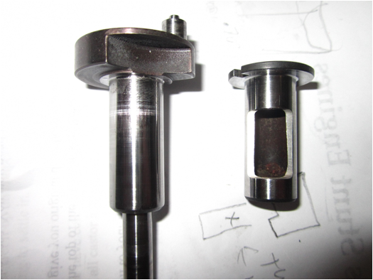
The drum rotor in this thing weighs nearly as much as the crankshaft, both are steel so I found and bought some aircraft aluminum on eBay. I intend to remake the drum rotor out of the aluminum.
This should bring the weight issue Boris has right in line with the current D motor, McGee .65. This part will be made after the snow subsides, it’s currently -18 deg c where I am and my visit to Greg will have to be after the thaw. Here is what the engine looks like today after losing a few pounds.
Back to Bod Busters main page
Back to Speed main page
Flying Lines home page
This page was upated Jan. 5, 2017