
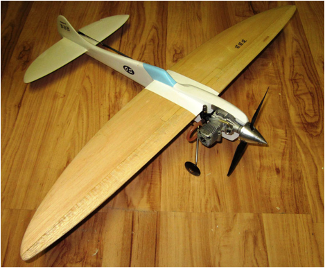
A View from Broadway
OS .25 part 2
Advanced rework
By Ken Burdick
Warning.
Yes folks it’s true,
but sadly not for everyone. I usually attempt to present information that most everybody can say “I get it,” or in a way that can easily be done, but this isn’t it. The advanced rework on the la .25 is such that if you are not experienced I suggest you do not do this stuff. You will likely create more problems than you know what to do with, but you can send the engine to someone who does have the skills and knowledge to make these changes to your engine, and I will list one or two of them at the end of this article. In the article you will see some tables that are meaningful to what we’re changing, so pay particular attention to the numbers associated with the crankshaft port. There are two areas of the chart.
· Depth reading
·
Port duration
The depth reading will tell us where the opening and closing
edge of the crankshaft port is. When one is changed, our port duration is going
to change and is expressed in degrees of crankshaft rotation..
Chaos
The absolute chaos that occurs inside a two cycle engine that is running is amazing and I don’t truly understand all of it, otherwise I would give you a precise step by step on exactly what to do. The basics make sense, but when you try to optimize it, is when things … get weird.
What I can tell you is if you measure very accurately and make some small changes and record the results, you will be able to detect if you have made any improvements.
In rough terms, we are going to attempt to increase the fuel and air charge into the cylinder head by taking in more fuel and air per revolution. It has to be done correctly or we’ll wind up with a very “peaky” engine that will have touchy needle setting so we are going to rely on the true experts for guidance.
Experts?
The experts in model engine performance are the engineers and
machinists who made countless experiments based on what they knew of two cycle
engine theory, metallurgy, and just plain old good work. Bill Wisniewski, Jaures
Garofali (supertigre) Cesare
Rossi, Clarence Lee, Bruce Tunberg, and perhaps the individual who changed how
modern high performance model engines are made today, Henry Nelson. These were
the people who took their understanding of the chaos I mentioned and made it
commercial. At one point, they were model airplane fliers just like you. All
received information from the radical element, which in various basements and
garages would experiment on engines, record exactly what they did and the
results of those changes.
Experimenters are people who understood
in depth the chaos, but had no desire to make their own business out of it. A
few of these individuals are Norm McFadden, Luke Roy, Tim Gillott, Jonh Newton,
Dave Williams. These and others like them, have a love of engines and an
extreme eye for detail.
If I have left out
one of your favorites, I apologize, there are many. All these names have fed
the manufactures information uniquely developed on their own. People who enjoy
the high performance and ease of our modern engines owe them all thanks.
Getting busy
We are going to focus on three primary areas.
· Exhaust duration
·
Intake duration/ crank shaft valve
·
Cylinder
head modifications
Let’s start out by comparisons to known good engines for
speed and racing. It’s always good to remember that if we do get some RPM
increase, it is likely going to narrow the power band of our engine, so having successful
examples is helpful in getting our project a bit further up the rpm scale
without going too far.
The Challenge
Remember, we are flying Geezer speed and not full on pipe F2A. A standing start 1 mile of 14 laps, so we’re looking for some modest gains out of an engine not designed to do what we are doing with it. To make matters worse, we are limited to 10% nitro. The event is dependent on acceleration from the instant the model is released, which means we cannot ignore the torque produced at the lower rpms and sacrifice it just for high rpms. If we did, we would wind up with a tiny prop and an engine that will give us no “hole shot” or fast acceleration. We need to swing a large enough prop to ideally get off the line and accelerate through much of the half mile, but small enough that we stay in the rpm “sweet spot.” Props are like gears for us, so once we get a decent engine; we can begin to find that perfect formula for our individual set up.
The following timing specs are as measured by myself and are
then put into a calculator designed by Luke Roy. They are our starting point that we will use as a
reference for our changes.
Intake timing
(Stock engine)
Our current crankshaft valve timing as I measure it is:
(Notice the
closing depth reading and total intake timing)
TGC Timing Calculator
|
|
||||||||||||||||||||||

![]()
|
|
|
|
Deck Height |
0.1830 |
|
Stroke / 2 |
0.3150 |
|
Rod/Stroke Ratio |
1.8413 |
|
Engine Displacement |
0.2487 |
|
Swept Volume from Exhaust Closing |
0.1765 |
|
Blow Down (DEG) |
16.48 |
|
Blow Down (Inches) |
0.0720 |
|
Exhaust
Port Values |
|
|
Distance ATC |
0.4470 |
|
Distance BBC (Port HGT) |
0.1830 |
|
Port Duration (DEG) |
145.96 |
|
Piston ATC (DEG) |
107.02 |
|
Piston BBC (DEG) |
72.98 |
|
Transfer
Port Values |
|
|
Distance ATC |
0.5190 |
|
Distance BBC (Port HGT) |
0.1110 |
|
Port Duration (DEG) |
113.00 |
|
Piston ATC (DEG) |
123.50 |
|
Piston BBC (DEG) |
56.50 |
|
Inlet
(Crank Port or Rotor) Values |
|
|
Port Opens ABC (DEG Crank Port or
Rotor) |
42.48 |
|
Port Opens BTC (DEG Crank Port or
Rotor) |
137.52 |
|
Port Close ATC (DEG Crank Port or
Rotor) |
42.40 |
|
*Total Intake Timing (DEG Crank Port or Rotor) |
*179.92 |
180 degree of crankshaft rotation is how long the port is open to its close.
The Nelson .40 is open a total of 194 deg and the St .15 is open 186 degrees of crank rotation so ours by comparison is a bit mild. Because of some variations I may have entered by my own measurements I will be very conservative. After that I will reassemble the engine and record the rpm changes.
Our first target is:
· 190 degrees of valve duration by leaving the valve open 10 degrees longer.
To do this we’ll need Luke’s calculator and plug in an
imaginary number on the closing side and then mark the crankshaft at this
number, and remove material until we get the closing number of 190 degrees.
First stop
The Grate Cajun Calculators http://www.doov.com/
We look up the timing calculator and input our stock engine measurements. Yep, that’s the one. 179.9 deg of intake duration. Now we’ll change the closing dimension from .285 to .340. That will make a big ol .055 change to remove from the closing side of the port. Not much to remove so you can see that small changes make big differences
Let’s get wild n
crazy and go for 190 deg of duration.
190 deg specs
(notice the change in depth close from stock .285 to .340)
TGC Timing Calculator
|
|
||||||||||||||||||||||
![]()
|
|
|
|
Deck Height |
0.1830 |
|
Stroke / 2 |
0.3150 |
|
Rod/Stroke Ratio |
1.8413 |
|
Engine Displacement |
0.2487 |
|
Swept Volume from Exhaust Closing |
0.1765 |
|
Blow Down (DEG) |
16.48 |
|
Blow Down (Inches) |
0.0720 |
|
Exhaust
Port Values |
|
|
Distance ATC |
0.4470 |
|
Distance BBC (Port HGT) |
0.1830 |
|
Port Duration (DEG) |
145.96 |
|
Piston ATC (DEG) |
107.02 |
|
Piston BBC (DEG) |
72.98 |
|
Transfer
Port Values |
|
|
Distance ATC |
0.5190 |
|
Distance BBC (Port HGT) |
0.1110 |
|
Port Duration (DEG) |
113.00 |
|
Piston ATC (DEG) |
123.50 |
|
Piston BBC (DEG) |
56.50 |
|
Inlet
(Crank Port or Rotor) Values |
|
|
Port Opens ABC (DEG Crank Port or
Rotor) |
42.48 |
|
Port Opens BTC (DEG Crank Port or
Rotor) |
137.52 |
|
Port Close ATC (DEG Crank Port or
Rotor) |
53.77 |
|
Total Intake Timing (DEG Crank Port or Rotor) )*increased to 191
deg made by .340 dim change above |
191.29 |
To get to 190 degree of duration we removed .055 from our original closing point and used a 8 x 5 power prop for rpm checks. We expect to see lower rpms using this prop.
Rpm @ 180 deg 16,850 ( 8 x 5 power prop)
RPM @ 190 deg 17100 ((8 x 5 power prop)
A nice gain of 250 RPM on a power absorbing prop.
Magic!
More air please…..

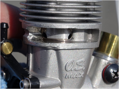
Sub-port induction
I said there would be magic, so here it is lil’ Geezers. We gotta have SOME fun, even reworking an engine!
The idea of sub port induction is to introduce air into the engine that the venturi cannot. Our primary source of air of course is the venturi, but they are only so big, but a small amount of piston skirt can be removed in the exhaust port, to introduce air into the engine. You may have seen this on the T D .049 or other old school engines, even as far back as the Atwood. Does it work? Yes, but you really need to be careful since it’s the piston we’re fooling around with here. If you are wondering if this really works, try it on a diesel sometime. You will get a lean running condition if too much material is removed and the venturi will need to be reduced for it to run correctly on suction again. This should be a warning that you are really messing with the fuel air ratio. So as they say, easy does it. Fortunately, glow engines are less sensitive to the introduction of air. If you use a mini pipe, I cannot recommend this, I don’t know why either. It is a consensus that the exhaust may in some way foul the air if there is any back pressure from a pipe. Bill Whisnewski did make a timed version of this idea. The holes went through the case, through the liner and were uncovered by the piston at the same opening and closing as the crank valve. There is no way exhaust can be funneled back into the combustion air since it enters the engine outside of the exhaust port. I am not confident in doing this so ain’t gonna….nada, nope, let me know how it turns out for you. It is however a very good idea that should also work with a full wave pipe. We geezers are going to play it safe and do what I know works for the purpose of this article. I’ll remove some of the piston skirt and then we’ll measure the rpm once again. (Sometime the next day)
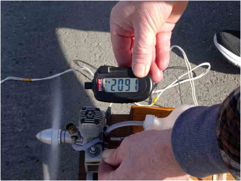
I have a bench prop bolted on and just ran our little monster on this 6.80 x 7.5 prop.
· Without sub port induction 19,200 rpm
·
With sub port induction 19,700
rpm
Here are some pictures from the mysterious Fast Hippie and his excellent results from sub port induction. The Hippioe has ported on both sides of the piston while I chose to just port in the center.
The Hippie’s engine
Propeller
Spend your time here.
If there is one place the speedy Geezer should focus, it’s here. Props are the gold mine of a speed event. Sure, we all like to focus on the engine….because it’s fun and mysterious, but props can be tweaked to create efficiency that dwarf our increases of engine rework. In a proto event like G speed, the best way to find your prop is to experiment. When you make a change, do so with a controlled purpose, just like with the crank port, make small changes and then fly with a stopwatch on it. When you compare notes to another G speed, be sure they are similar enough in weight for this.
The APC prop is a good place to begin. Proto speed in the old days used 8 x 8 speed props, lots of Nitro and the tweaking would start there. Those were nitro burners so we cannot swing this kind of prop on 10% nitro and do well. The APC 8 x 8 may be a good starting place and modify the diameter. An 8 x 7 might be a better place to begin and remember, not all props are the same. My suggestion is to decide on how much work you want to put into the engine, do it, then fiddle around the 7 x 7 to 8 x 7 range, recording changes. Once you get decent speeds, step up to the plate and contact Mike Hazel for a custom made prop from ZZ Prop. zzclspeed@aol.com
I am not sure what ZZ has for this event, but he’s always got something up his sleeve for lil Geezers wanting to fly speed. Another good source is Steve Wilks at Eliminator props. http://eliminatorprops.com/store/index.php?main_page=advanced_search_result&search_in_description=1&keyword=m%203&inc_subcat=0&sort=20a&page=7
Steve has a wide variety of props to choose from. They are
rough molded but with 15 min of work you can have a winner of a prop.
Stay out of the E.R.!
We do NOT want to hand flip these razor sharp things so use a starter or you may well be in the ER. Chicken sticks will damage the fine edge these nice props can have, so approach carbon fibre props with respect…..besides they can be expensive. When you do sand the flashing off the prop, be sure to wear a filter mask as the sharp pieces carbon dust are nothing we Geezers or non Geezers want to be keeping in our lungs.
I have selected four of the Eliminator props to range our little project with, and as you can see I have varied the sizes less than 8 x 8 so I can learn what this engine likes for a proto event. Each prop has a different blade shape and as a result, will give different power. The props that will get you the best times are not represented by my test props. They are trying to simulate rpm that we might see in the air in an unloaded condition while flying. Do not be discouraged if your ground rpm is substantially different from my figures here……we wanna see what the stop watch says, not the tachometer.
Eliminator Props selected
G-6 G-6 7 X 7
G-6 7 X 7 This prop is based on Graupner Electric Speed Prop 7 X 7.
1/4" Shaft hole This prop is sold unfinished.
T-5 7
X 7 1/2
7 X 7 1/2 This prop is based on Taipan 7X6 prop re-pitched. 5-16" Shaft hole This prop is sold unfinished.
B-8 B-8 7 1/2X 7
B-8 7 1/2X 7 This prop is based on Eichenberger Prop. B Speed
5/16" Shaft hole This prop is sold unfinished.
G-1 G-1 8 X 6 1/2
G-1 8 X 6 1/2 This prop is based on Graupner prop. 1/4”" Shaft
hole This prop is sold unfinished
One more Time!
Best RPM recorder was 19,700 open faced on a bench prop. I would imagine this is likely to be the rpm I will see in the air, but who knows. Now the real testing can begin with what really matters…the stopwatch.
You take it from here
I have tried to take you through a responsible method of
reworking the O.S. LA .25 for use in the N.W. B proto speed event. For all
changes, I have tried to eliminate the BS factor and stick to the facts. You
will not gain anything from grinding away at the head, case or other parts of
this engine. If you want a lighter set up, build a lighter airplane, if you
want it to run hotter, put an o-ring around the cylinder fins. Is there more
speed to be had from the engine? Yes, but we are not going there without some
really sophisticated tools and machines. This will get the horse out of the
barn for ya.
Well that about concludes our review and rework of the OS
.25 for Geezer
Speed. We have taken a perfectly good sport engine and turned it into
something that is capable of some decent performance for a speed event. Good
luck.
Kennyb
Equipment sources:
This page was updated April 27,
2015